


Input / Output 4-13MN1928
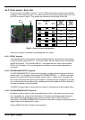
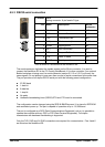
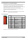
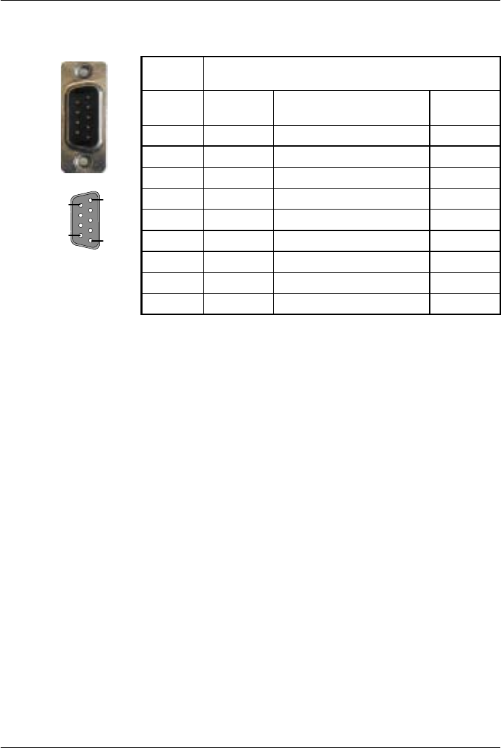
4.5.3 RS232 serial connection
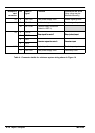
Location Serial
Mating connector: 9-pin female D-type
Pin Name Description 96-pin
connector
1 Shield Shield connection a32
2 RXD Receive Data a20
3 TXD Transmitted Data a21
4 (NC) (Not connected) a16*
5 DGND Digital ground a3
6 (NC) (Not connected) a17*
7 RTS Request To Send b21
8 CTS Clear To Send a22
9 DGND Digital ground a3
* Pins a16 and a17 are linked on the NextMove ES.
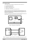
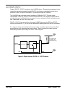
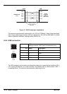
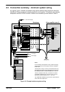
The serial connector duplicates the signals present on the 96-pin connector. It is used to
connect the NextMove ES to the PC running WorkBench v5, or other controller. If an optional
Baldor backplane is being used, its serial connector (section 5.2.13 or 5.3.13) will carry the
same signals. Do not attempt to use more than one set of serial connections at the same time.
The port provides a full-duplex RS232 serial port with the following preset configuration:
H 57,600 baud
H 1startbit
H 8 data bits
H 1stopbit
H No parity
H Hardware handshaking lines (RS232) RTS and CTS must be connected.
The configuration can be changed using the SERIALBAUD keyword. It is stored in EEPROM
and restored at power up. The port is capable of operation at up to 1 15,200 baud.
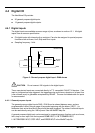
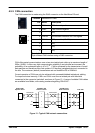
The port is configured as a DCE (Data Communications Equipment) unit so it is possible to
operate the controller with any DCE or DTE (Data Terminal Equipment). Full duplex
transmission with hardware handshaking is supported.
Only the TXD, RXD and 0V GND connections are required for communication. Pins 4 and 6
are linked on the NextMove ES.
1
5
6
9