


4-12 Input / Output MN1928
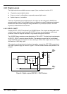
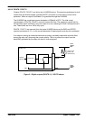
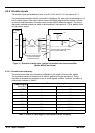
4.5.2 Encoder inputs
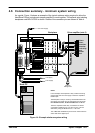
The encoder inputs are available on pins a7-a10, b7-b10 and c7-c10. See section 4.2.1.
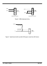
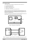
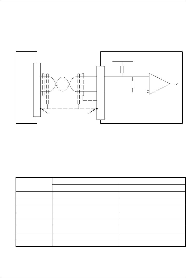
Two incremental encoders may be connected to NextMove ES, each with complementary A, B
and Z channel inputs. Each input channel uses a MAX3095 differential line receiver with pull
up resistors and terminators. Encoders must provide RS422 differential signals. The use of
individually shielded twisted pair cable is recommended. See section 8.1.10 for details of the
encoder power supply.
CHA-
CHA+
to CPU
Vcc
NextMove ES
MAX3095
120R
10k
b7
b10
Shield
a32
Connect overall shield to
connector backshells /
shiel d connections.
Twisted pai r
MicroFlex
X7 encoder
output
a11
DGND
Connect internal shield to DGND.
Do not connect other end.
1
6CHA-
CHA+
Figure 11 - Encoder channel input - typical connection from a servo am plifie r
(Baldor MicroFlex shown)
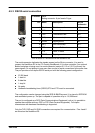
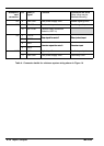
4.5.2.1 Encoder input frequency
The maximum encoder input frequency is affected by the length of the encoder cables.
The theoretical maximum frequency is 20 million quadrature counts per second. This is
equivalent to a maximum frequency for the A and B signals of 5MHz. However, the effect of
cable length is shown in Table 3:
A and B signal
Maximum cable length
A
a
n
d
B
s
i
g
n
a
l
frequency
meters feet
1.3MHz 2 6.56
500kHz 10 32. 8
250kHz 20 65. 6
100kHz 50 164.0
50kHz 100 328.1
20kHz 300 984.2
10kHz 700 2296.6
7kHz 1000 3280.8
Table 3 - Effect of cable length on maximum encoder frequency