


5-2 Input / Output MN1928
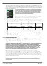
5.2 BPL010-501 non-isolated backplane
This backplane provides direct connection to the NextMove ES signals without isolation. The
electrical specifications of all signals are therefore the same as described in section 4.
In the following sections, the signals AGND, DGND and Shield are listed with nominal
corresponding pins on the 96-pin connector, although they are all electrically connected on the
backplane. The OUT COM pin on connector X1 1 is not connected to ground.
Some signals are duplicated on multiple identically named pins on the 96-pin connector.
In these cases, only the lowest numbered pin is listed.
CAUTION: Some components are static sensitive devices. Take appropriate ESD
precautions when handling the backplane.
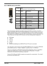
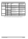
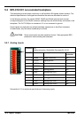
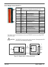
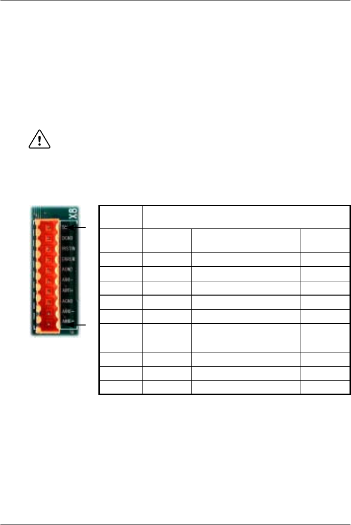
5.2.1 Analog inputs
Location X8
Mating connector: Weidmüller Omnimate BL 3.5/10
Pin Name Description 96-pin
connector
10 Shield Shield connection a32
9 DGND Digital ground a3
8 !RSTIN Reset input c12
7 ERROR Error output b11
6 AGND Analog ground a30
5 AIN1- Analog input AIN1- a27
4 AIN1+ Analog input AIN1+ c28
3 AGND Analog ground a30
2 AIN0- Analog input AIN0- a28
1 AIN0+ Analog input AIN0+ b28
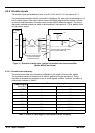
See section 4.3.1 for electrical specifications of the analog inputs.
1
10