


Operation 6-11MN1928
6.5 Servo axis - testing and tuning
This section describes the method for testing and tuning a servo axis. The amplifier must
already have been tuned for basic current or velocity control of the motor.
6.5.1 Testing the demand output
This section tests the operation and direction of the demand output for axis 4. By default, axis
4 is a servo axis (although it can be reconfigured as a stepper - see section A.1). It is
recommended that the motor is disconnected from the load for this test.
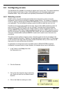
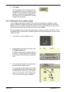
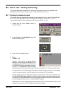
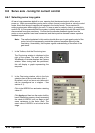
1. Check that the Drive enable button is
pressed (down).
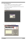
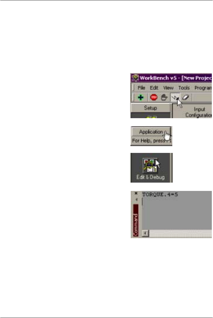
2. In the Toolbox, click Application t hen click
the Edit & Debug icon.
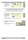
3. Click in the Command window .
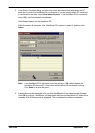
4. Type:
TORQUE.4=5
where 4 is the axis to be t ested. In this
example, thisshould cause ademand of+5%
of maximum output (0.5V) to be produced at
the DEMAND0 output (backplane connector
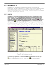
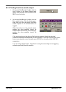
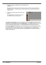
X7, pin 1). In WorkBench v5, look at the Spy
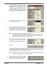
window located on the right of the screen. In the Axis selection box at the top, select Axis 4.
The Spy window’s Command display should show 5 percent (approximately). If there seems
to be no command output, check the electrical connections on the backplane.
TheSpy window’s Ve locity display should show apositivevalue. Ifthe value is negat ivecheck
that the DEMAND0 output, and the Encoder0 A and B channels, have been wired correctly.
If necessary ,the ENCODERMODEkeyword canbe usedto swapthe encoderA and Bchannels,
thus reversing the encoder count - see the MintMT help file.
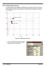
By default, axis 4 uses demand output 0and encoder 0, andaxis 5 u ses demand output 1 and
encoder 1. See section 4.3.2 for details of the demand outputs.