


Input / Output 5-21MN1928
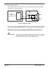
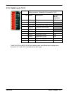
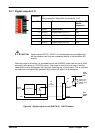
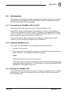
5.3.7 Digital outputs 8-11
Location X5
Mating connector: Weidmüller Omnimate BL 3.5/5
Pin Name Description NextMove ES
96-pin
connector
5 DGND Digital ground a3
4 DOUT11 Digital output DOUT11 c22
3 DOUT10 Digital output DOUT10 c16
2 DOUT9 Digital output DOUT9 b13
1 DOUT8 Digital output DOUT8 a13
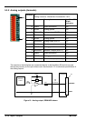
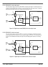
CAUTION: Digital outputs DOUT8 - DOUT11 on the backplane are not buffered by
the opto-isolator card; they are connected directly to the NextMove ES
outputs.
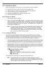
When an output is activated, it is grounded through the ULN2003, which can sink up to 50mA
per output (all outputs on, 100% duty cycle). If an output is used to drive a relay, a suitably
rated diode must be fitted across the relay coil, observing the correct polarity. This is to protect
the output from the back-EMF generated by the relay coil when it is de-energized.
DOUT8
NextMove ES
ULN2003
MintMT
OUTX.8
74AHCT244
DGND
GND
User
supply
24V
User
supply
GND
Backplane
1
96
pin
connector
’X5’
5
Output Load
(Relay with
flyback diode
shown)
Figure 24 - Digital output circuit (DOUT8-11) - DOUT8 shown
1
5