


4-18 Input / Output MN1928
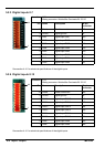
Backplane
card
connector
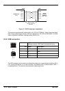
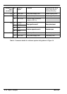
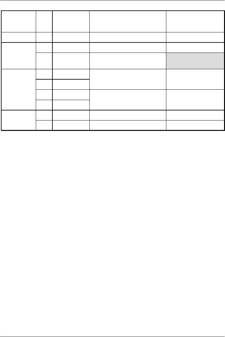
Pin Name of
signal
Function Connection on drive
(Note: drive may be
labelled dif ferently)
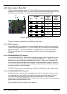
X6 9 USR GND User power supply GND Enable signal ground
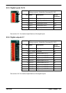
X8 9 REL NO Switched relay contact Enable signal input
10 REL COM C ommon relay connection
(linkedtoUSRV+)
X9 2 STEP0-
S
t
e
p
s
i
g
n
a
l
f
o
r
a
x
i
s
0
S
t
e
p
(
p
u
l
s
e
)
i
n
p
u
t
3 STEP0+
S
t
ep s
i
gna
l
f
or ax
i
s
0
S
t
ep
(
pu
l
se
)
i
npu
t
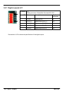
4 DIR0 -
D
i
r
e
c
t
i
o
n
s
i
g
n
a
l
f
o
r
a
x
i
s
0
D
i
r
e
c
t
i
o
n
i
n
p
u
t
5 DIR0+
D
i
rec
t
i
on s
i
gna
l
f
or ax
i
s
0
D
i
rec
t
i
on
i
npu
t
X12 1 DIN0 Digital input 0 Fault relay output
11 USR GND User power supply GND Fault relay GND
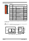
Table 4 - Connector details for minimum system wiring shown in Figure 14