


Input / Output 4-7MN1928
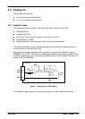
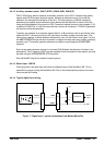
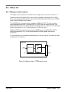
4.4.1.2 Auxiliary encoder inputs - DIN17 (STEP), DIN18 (DIR), DIN19 (Z)
DIN17-DIN19 may also be used as an auxiliary encoder input. DIN17 accepts step (pulse)
signals and DIN18 accepts direction signals, allowing an external source to provide the
reference for the speed and direction of an axis. The step frequency (20MHz maximum)
determines the speed, and the direction input determines the direction of motion. Both the
rising and falling edges of the signal on DIN17 cause an internal counter to be changed. If 5V
is applied to DIN18 (or it is left unconnected) the counter will increment. If DIN18 is grounded
the counter will be decremented.
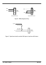
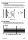
Typically , one channel of an encoder signal (either A or B) would be used to provide the step
signal on DIN17, allowing the input to be used as an auxiliary (master) encoder input. The
input can be used as a master position reference for cam, fly and follow move types. For this,
the MASTERSOURCE keyword must be used to configure the step input as a master (auxiliary)
encoder input. The master position reference can then be read using the AUXENCODER
keyword.
Since a secondary encoder channel is not used, DIN18 allows the direction of motion to be
determined. The Z signal on DIN19 can be supplied from the encoder’s index signal, and may
be read using the AUXENCODERZLATCH keyword.
See the MintMT help file for details of each keyword.
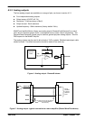
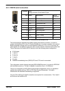
4.4.1.3 Reset input - !RSTIN
When grounded, the reset input will cause a hardware reset of the NextMove ES. This is
equivalent to power-cycling the NextMove ES. Due to the internal pull-up resistor, the reset
input may be left floating.
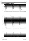
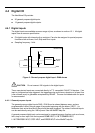
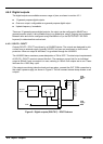
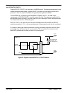
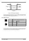
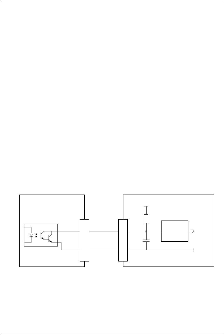
4.4.1.4 Typical digital input wiring
DGND
DIN0
GND
MintMT
INX.0
+5V
NextMoveES
10k
74AHCT14
1nF
c21
a3
Status+
Status-
3
2
MicroFlex / equipment output
NEC PS2562L-1
Figure 7 - Digital input - typical connections from Baldor MicroFlex