


Index
MN1928
encoder inputs, 4-12, 8-4
error output, 4-10
serial port, 4-13
stepper control outputs, 4-11, 8-4
USB port, 4-14
Installation, 3-1
Introduction to closed loop control, 6-13
Isolated backplanes, 5-11
L
LED indicators
status display, 7-2
surface mount, 7-3
Loading saved information, 6-30
N
Non-isolated backplane, 5-2
X1 screw terminal block, 5-9
X2 Encoder1 D-type connector, 5-10
X3 Encoder0 D-type connector, 5-9
X4 Serial D-type connector , 5-10
X5 screw terminal block, 5-6
X6 screw terminal block, 5-5
X7 screw terminal block, 5-3
X8 screw terminal block, 5-2
X9 screw terminal block, 5-7
X10 screw terminal block, 5-8
X11 screw terminal block, 5-5
X12 screw terminal block, 5-4
X13 screw terminal block, 5-4
O
Operation, 6-1
connecting to the PC, 6-1
installing the USB driver , 6-2
installing WorkBench v5, 6-1
power on checks, 6-2
preliminary checks, 6-2
starting, 6-1
Opto-isolated backplanes, 5-11
X1 screw terminal block, 5-24
X2 Encoder1 D-type connector, 5-25
X3 Encoder0 D-type connector, 5-24
X4 Serial D-type connector , 5-25
X5 screw terminal block, 5-21
X6 screw terminal block, 5-17
X7 screw terminal block, 5-14
X8 screw terminal block, 5-12
X9 screw terminal block, 5-22
X10 screw terminal block, 5-23
X11 screw terminal block, 5-19
X12 screw terminal block, 5-15
X13 screw terminal block, 5-16
active-high inputs, 5-18
active-low inputs, 5-18
NPN outputs, 5-20
PNP outputs, 5-20
relay connections, 5-13
Overdamped response, 6-19
P
Power sources, 3-2, 8-1
Precautions, 1-2
R
Receiving and Inspection, 2-3
Relay
DRIVEENABLEOUTPUT keyword, 4-10
GLOBALERROROUTPUT keyword, 4-10
opto-isolated backplanes, 5-13
RELAY keyword, 4-10
RS232 port, 4-13
S
Safety Notice, 1-2
Saving setup information, 6-29
Scale, selecting, 6-6
Serial connector, 4-13
Servo axis, 6-11
adjusting KPROP, 6-25
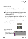
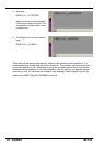
eliminating steady-state errors, 6-21
testing the demand output, 6-11
tuning for current control, 6-16
tuning for velocity control, 6-22
Specifications, 8-1
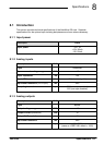
analog inputs, 8-1
analog outputs (demands), 8-1
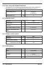
CAN interface, 8-4
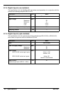
digital inputs, 8-2
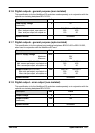
digital outputs, 8-3
encoder inputs, 8-4
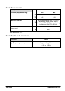
environmental, 8-5
error output, 8-3, 8-4