


Input / Output 4-17MN1928
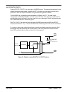
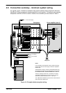
4.6 Connection summary - minimum system wiring
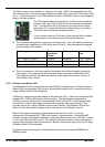
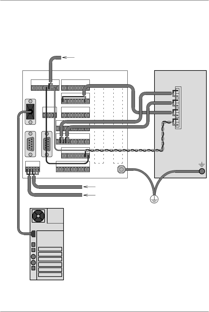
As a guide, Figure 14 shows an example of the typical minimum wiring required to allow the
NextMove ES and a single axis stepper amplifier to work together. The optional opto-isolating
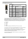
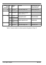
backplane card BPL010-502 is shown. Details of the connector pins are shown in Table 4.
Backplane
X1
Pulse+
Gnd
Enable
Direction+
Pulse-
Fault relay
Host PC
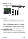
Notes:
In this ex ample, the backplane’s relay contacts are being
used to apply the 24V user supply to the drive amplifier’s
Enable input.
The backplane’ s relay is driven by the NextMov e ES Error
Out signal. This signal may be controlled by the k eywords
DRIVEENABLEOUTPUT, GLOBALERROROUTPUT or RELAY.
The drive amplifier’s Fault relay connections are shown
connected to di gital input 0. If an error occurs, it can be
detected by using the MintMT Event IN0 event.
The INPUTACTIVELEVEL keyword can be used to alter the
active state of the digital input.
Drive amplifier (axis 0)
Common
earth/ground
Encoder0 Encoder1
Serial
X4
X2 X3
X7
X5
X8
X9
X10
X11
X12
X13
X6
+24V user supply
Direction-
NextMove ES
Gnd
±12V supply
+5V supply
Figure 14 - Example minimum system wiring