


Index
MN1928
power , 8-1
relay, 8-4
stepper outputs, 8-4
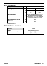
weights and dimensions, 8-5
Status display, 7-2
Stepper axis, 6-10
control outputs, 4-11
testing the output, 6-10
T
Testing
servo axis, 6-11
stepper axis, 6-10
Troubleshooting, 7-1
communication, 7-4
help file, 6-3
motor control, 7-4
problem diagnosis, 7-1
status display, 7-2
SupportMe, 7-1
WorkBench v5, 7-5
Tuning
adjusting KPROP, 6-25
axis for velocity control, 6-22
calculating KVELFF, 6-22
critically damped response, 6-20
eliminating steady-state errors, 6-21
overdamped response, 6-19
selecting servo loop gains, 6-16
underdamped response, 6-18
U
Underdamped response, 6-18
Units and abbreviations, 2-4
USB
installing the driver, 6-2
port, 4-14
W
Weights and dimensions, 8-5
WorkBench v5, 6-3
digital input/output configuration, 6-27
help file, 6-3
loading saved information, 6-30
saving setup information, 6-29
starting, 6-4
X
X1 screw terminal block
non-isolated backplane, 5-9
opto-isolated backplanes, 5-24
X2 Encoder1 D-type connector
non-isolated backplane, 5-10
opto-isolated backplanes, 5-25
X3 Encoder0 D-type connector
non-isolated backplane, 5-9
opto-isolated backplanes, 5-24
X4 Serial connector
non-isolated backplane, 5-10
opto-isolated backplanes, 5-25
X5 screw terminal block
non-isolated backplane, 5-6
opto-isolated backplanes, 5-21
X6 screw terminal block
non-isolated backplane, 5-5
opto-isolated backplanes, 5-17
X7 screw terminal block
non-isolated backplane, 5-3
opto-isolated backplanes, 5-14
X8 screw terminal block
non-isolated backplane, 5-2
opto-isolated backplanes, 5-12
X9 screw terminal block
non-isolated backplane, 5-7
opto-isolated backplanes, 5-22
X10 screw terminal block
non-isolated backplane, 5-8
opto-isolated backplanes, 5-23
X11 screw terminal block
non-isolated backplane, 5-5
opto-isolated backplanes, 5-19
X12 screw terminal block
non-isolated backplane, 5-4
opto-isolated backplanes, 5-15
X13 screw terminal block
non-isolated backplane, 5-4
opto-isolated backplanes, 5-16