


5-10 Input / Output MN1928
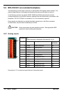
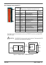
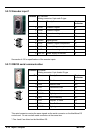
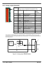
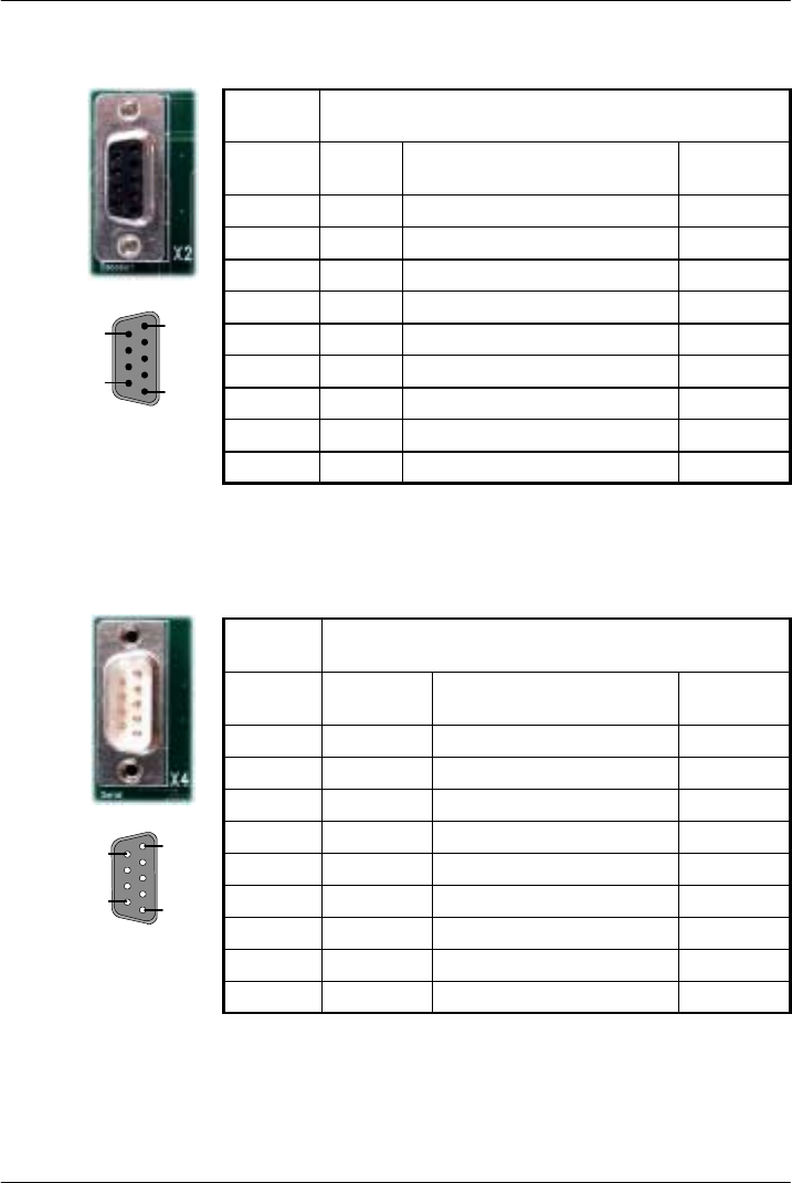
5.2.12 Encoder input 1
Location X2 Encoder1
Mating connector: 9-pin male D-type
Pin Name Description 96-pin
connector
1 CHA+ Channel A signal a8
2 CHB+ Channel B signal c7
3 CHZ+ Index channel signal c8
4 Shield Shield connection a32
5 DGND D igital ground a1
6 CHA- Channel A signal complement c9
7 CHB- Channel B signal complement a10
8 CHZ- Index channel signal complement a9
9 +5V out Power supply to encoder a1
See section 4.5.2 for specifications of the encoder inputs.
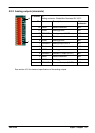
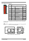
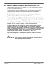
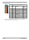
5.2.13 RS232 serial communication
Location X4 Serial
Mating connector: 9-pin female D-type
Pin Name Description 96-pin
connector
1 Shield Shield connection a32
2 RXD Receive Data a20
3 TXD Transmitted Data a21
4 (NC) (Not connected) a16*
5 DGND Digital ground a3
6 (NC) (Not connected) a17*
7 RTS Request To Send b21
8 CTS Clear To Send a22
9 DGND Digital ground a3
This serial connector carries the same signals as the serial connector on the NextMove ES
control card. Do not use both serial connectors at the same time.
*Pins4and6arelinkedontheNextMoveES.
1
5
6
9
1
5
6
9