


Index
MN1928
A
Abbreviations, 2-4
Analog I/O, 4-3
analog inputs, 4-3
analog outputs, 4-5
Auxiliary encoder inputs, 4-7
B
Backplanes
BPL010-501 non-isolated, 5-2
BPL010-502/503 opto-isolated, 5-11
catalog numbers, 5-1
introduction, 5-1
Basic Installation, 3-1
location requirements, 3-1
NextMove ES card, 3-2
C
Calculating KVELFF, 6-22
CAN interface
connection, 4-15
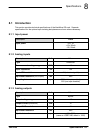
specifications, 8-4
Catalog number , identifying, 2-3
Closed loop control, an introduction, 6-13
Command outputs. See Demand outputs
Configuration
axis, 6-6
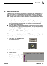
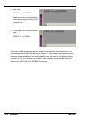
axis renumbering, A-1
digital inputs, 6-27
digital outputs, 6-28
selecting a scale, 6-6
setting the drive enable output, 6-7
testing a stepper axis, 6-10
testing and tuning a servo axis, 6-11
testing the drive enable output, 6-9
Connectors
96-pin edge connector, 4-1–4-2
CAN, 4-15
RS232, 4-13
USB, 4-14
Critically damped response, 6-20
D
Demand outputs, 4-5, 6-11
Digital I/O, 4-6
auxiliary encoder inputs, 4-7
configuration, 6-27
digital inputs, 4-6
digital outputs, 4-8
error output, 4-10
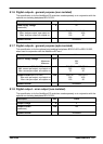
general purpose inputs, 4-6
reset input, 4-7
Drive enable output
DRIVEENABLEOUTPUT keyword, 4-10
setting, 6-7
testing, 6-9
E
Encoder inputs, 4-12
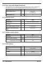
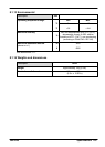
Environmental, 3-1, 8-5
Error output, 4-10, 8-3, 8-4
F
Features, 2-1
Feedback, 4-12, 5-9, 5-24, 8-4
H
Hardware requirements, 3-2
Help file, 6-3
I
Indicators, 7-2
status display, 7-2
surface mount LEDs, 7-3
Input / Output, 4-1
96-pin edge connector, 4-1
analog inputs, 4-3, 8-1
analog outputs, 4-5, 8-1
CAN connection, 4-15
connection summary, 4-17
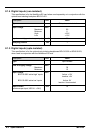
digital inputs, 4-6, 8-2
digital outputs, 4-6, 4-8, 8-3
Index