


Heat & Glo • RED60 • 2159-900 Rev. R • 9/1284
H. SheetMetalRefractoryInstructions
A Sheet Metal Refractory Kit is available for use with the
RED60 models. This kit contains the components neces-
sary to install metal refractory on the RED60-NNN model.
Install Sheet Metal Refractory Kit according to these in-
structions.
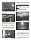
CAUTION! Risk of Cuts or Abrasions. Wear protective
gloves and safety glasses during installation. Sheet metal
edges are sharp.
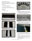
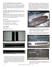
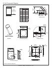
Figure1.OutsideCornerTrimPieces.
ToolsRequired
Cordless Drill
1/4 inch hex head driver tip
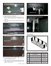
KitContents:
(2) Outside corner trim pieces. See Figure 1.
(1) Front Inside base. See Figure 2.
(1) Rear Inside base. See Figure 2.
(1) Outside front trim base. See Figure 3.
Figure2.FrontandRearInsideBasePiece.
Figure3.OutsideFrontTrimBasePiece.
NOTICE: The installation of the sheet metal refractory kit
may require the air shutter setting to be changed. See
Section 14.K of this manual to ensure the shutter gap is
set correctly before ring the appliance.
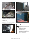
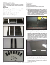
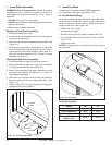
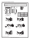
1. Install rear inside base piece. Position piece into bottom
of replace with tabs facing the burner. Center piece
from front to back. There will be a gap between the front
edge of the base piece and the burner area and also a
gap between the back of the base piece and the rear
rebox panel. These two gaps should be equal. See
Figure 4.
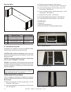
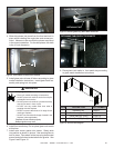
3. Install glass frame assembly and spring lock into posi-
tion according to instructions in appliance installation
manual. Set access panel into position.
4. Position access panel so tabs are facing the glass
assembly. Insert into glass frame. See Figure 5.
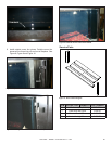
Figure4.PlacingBasePieces.
TABS
ALLGAPSEQUAL
Figure6.AccessPanelInstalled.
Figure5.PositioningAccessPanel.
TABS FACE GLASS
ASSEMBLY
GLASSASSEMBLY
GLASSASSEMBLY
ACCESSPANEL
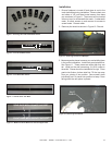
5. Place outside front trim base onto access panel. Place
so the cutouts are in line with the outside edges of the
glass frame. See Figure 7.
2. Install front inside base piece. Position piece into bot-
tom of replace with tabs facing the outside edge of the
rebox. Center from front to back. There will be a gap
between the front edge of the base piece and the front
of the rebox and also a gap between the back of the
base piece and the burner rail. These two gaps should
be equal. See Figure 4.