


Heat & Glo • RED60 • 2159-900 Rev. R • 9/12 43
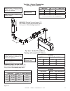
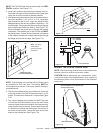
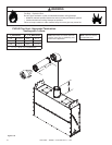
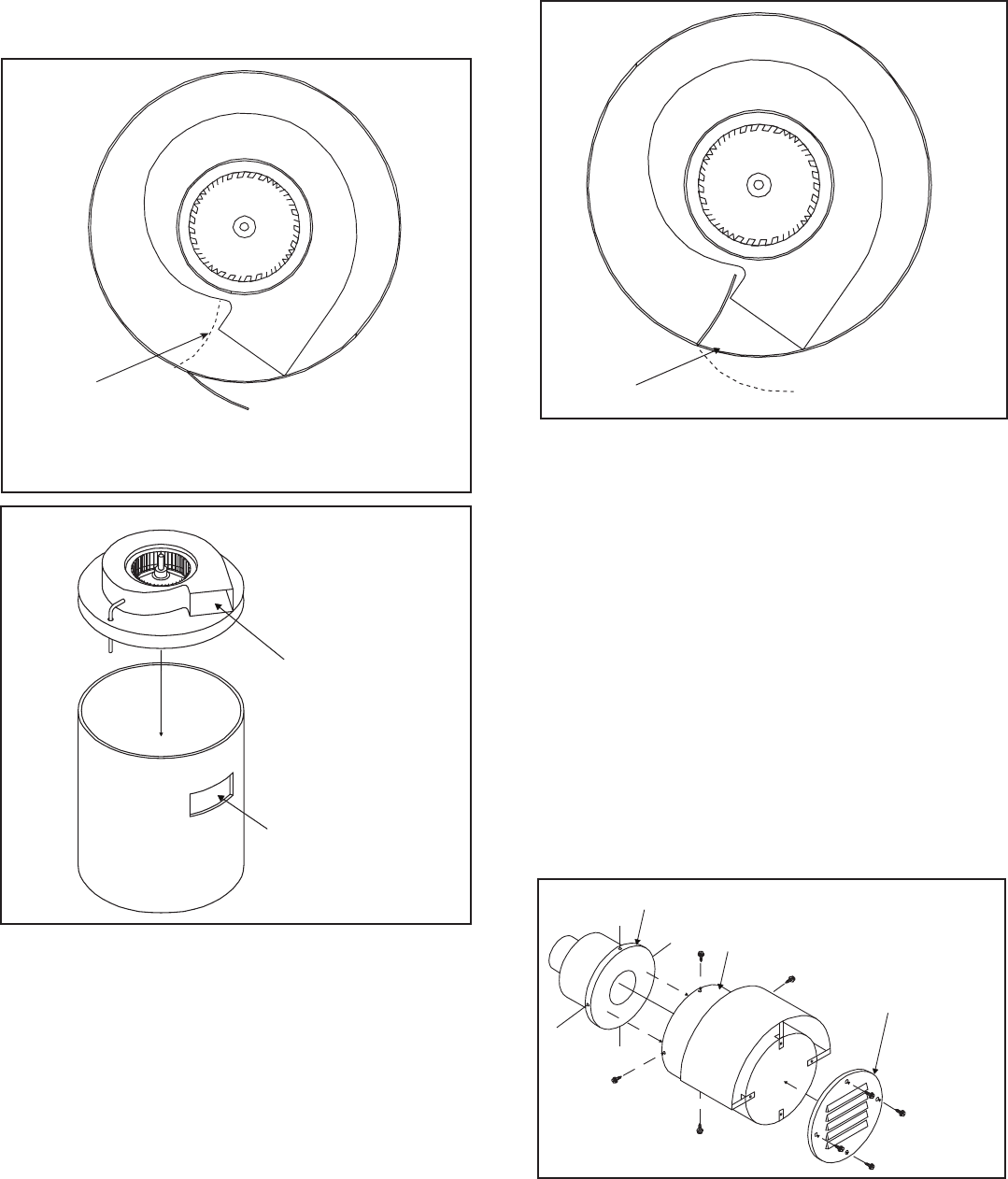
METAL GUIDE PLATE
MUST BE IN POSITION
AS SHOWN
Figure7.42
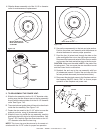
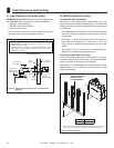
H. Slide the blower assembly out of the 10-1/2 in. diameter
collar for maintenance or replacement.
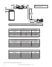
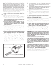
FAN
EXHAUST
PORT
EXHAUST
HOLE
Figure7.43
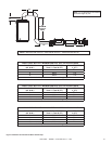
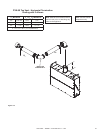
METAL GUIDE PLATE
Figure7.44
2. TOREASSEMBLETHEPOWERVENT:
A. Slide the fan assembly into the 10-1/2" diameter collar,
making sure that the exhaust port on the fan assembly
lines up with the exhaust hole cut in the 10-1/2" diameter
collar. See Figure 7.43.
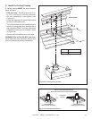
B. The metal exhaust guide plate will have to be bent back
inside the fan assembly. See Figure 7.44.
C. Fasten the wire mesh to the 10-1/2" collar to cover the
exhaust port hole, using (4) sheetmetal screws.
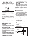
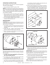
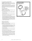
D. Slide the inner ring inside the cap assembly, carefully
positioning the inner ring to its original orientation. See
Figure 7.45. Carefully align the screw holes on the 10-
1/2" diameter collar and the inner ring.
NOTE: This inner ring must be returned to its correct ori-
entation with the 10-1/2" collar for proper fan operation.
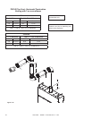
E. Secure the cap assembly to the last vent pipe section.
Position the power vent assembly with the exhaust air
directed downward to ensure proper operation.
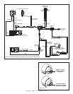
F. Feed the four (4) wires back through the hole on the
collar and tighten the nut on the right angle connector.
Reconnect the brown and red wire to the vacuum switch
and connect the black and white wires to the fan motor.
CAUTION: Make sure the cable is NOT in the path of the
hot exhaust air. This can cause the wire insulation to melt
and the Power Vent to malfunction.
G. Reattach the end cap to the cap assembly with four
(4) sheetmetal screws. Position the end cap with the
louvers pointed downward (horizontal termination).
H. Reconnect the electrical power to the replace and turn
the replace ON/OFF switch "ON" to ensure proper
operation of the replace and power vent.
END CAP
COLLAR
INNER RING
Figure7.45