


Heat & Glo • RED60 • 2159-900 Rev. R • 9/1264
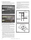
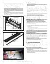
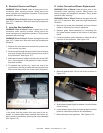
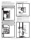
Figure12.7JunctionBoxDetail
1. Remove the one screw that secures the junction box
to the control tray panel.
2. Route the wire through the strain relief in the outer wrap
and down through the knockout located on top side of
the junction box. See Figure 12.7.
3. Make the connection inside the junction box to the 120V
wire. Connect green to the ground nut, black to black,
and white to white.
4. To reattach the junction box, insert one end of the
junction box in the slot provided and securely screw the
other end of the junction box to the control tray panel.
E. ElectricalServiceandRepair
WARNING! Risk of Shock! Label all wires prior to dis-
connection when servicing controls. Wiring errors can
cause improper and dangerous operation. Verify proper
operation after servicing.
WARNING! Risk of Shock! Replace damaged wire with
type 105° C rated wire. Wire must have high temperature
insulation.
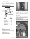
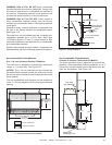
In the event that the junction box may need to be ac-
cessed or installed after nish methods have been ap-
plied, access is possible by removing the valve assembly
(See Figure 11.2).
KNOCKOUT
G. ActiveConvectionBlowerReplacement
WARNING! Risk of Shock! Label all wires prior to dis-
connection when servicing controls. Wiring errors can
cause improper and dangerous operation. Verify proper
operation after servicing.
WARNING! Risk of Shock! Replace damaged wire with
type 105° C rated wire. Wire must have high temperature
insulation.
F. JunctionBoxInstallation
WARNING! Risk of Shock! Label all wires prior to dis-
connection when servicing controls. Wiring errors can
cause improper and dangerous operation. Verify proper
operation after servicing.
WARNING! Risk of Shock! Replace damaged wire with
type 105° C rated wire. Wire must have high temperature
insulation.
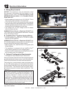
1. Remove re screen door assembly and any external
media or refractory from front of appliance.
2. Remove glass frame assembly by unlatching the
four glass latches located at the bottom of the glass
frame.
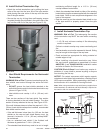
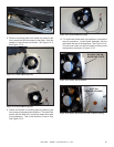
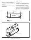
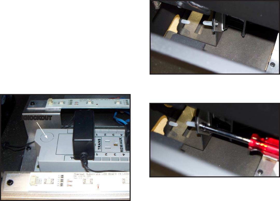
3. Locate the blower mount fastener on either the left or
right side of the appliance. See Figure 12.8.
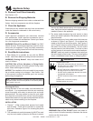
Figure12.9RemoveFastener
4. Remove fastener with 1/4 inch nut driver as shown in
Figure 12.9.
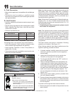
5. Slide blower forward slightly to release it from the blower
mount housing.
6. Locate blower power wires and unplug them from their
locations. Note these positions for reinstallation.
7. Remove blower from appliance. See Figure 12.10.
Figure12.8BlowerMountFastenerLocation