


Heat & Glo • RED60 • 2159-900 Rev. R • 9/12 39
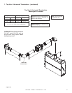
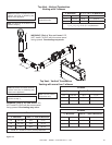
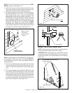
NOTE: The PVK-80 Power Vent must terminate in a HORI-
ZONTAL position. See Figure 7.31.
2. Install vent system components per planned vent run.
Route the vent pipe from the replace to the Power Vent
using the minimum number of elbows possible.
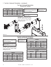
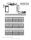
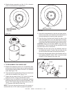
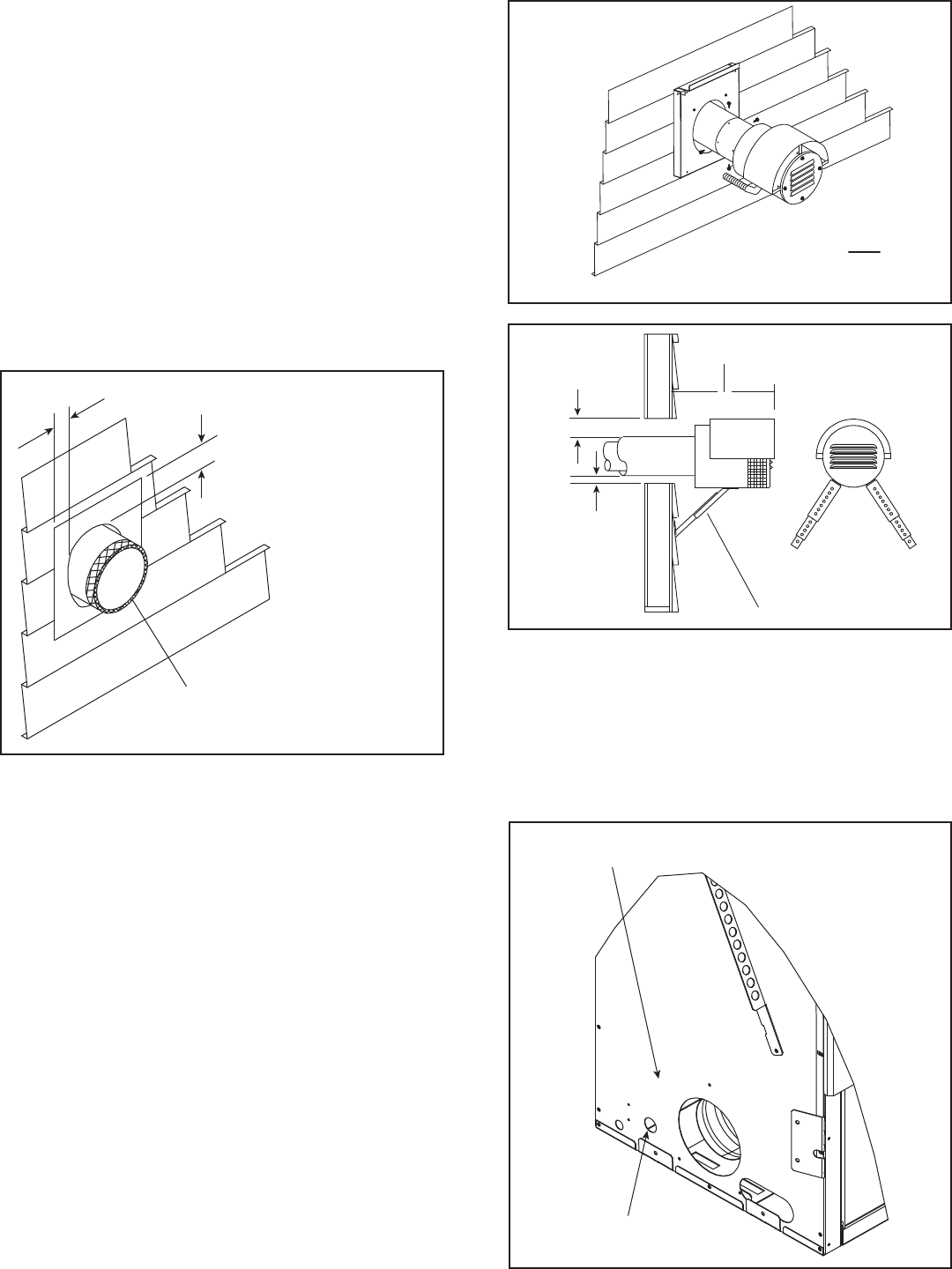
3. After determining the location of the vent system termina-
tion point (see Step 1) cut a 10 in. X 12 in. rectangular
hole through the wall or roof. Apply the adhesive back
berglass tape to the last vent system component 1 1/4"
from the edge. Firmly press the tape on to the venting and
fold the extra tape inside the venting. See Figure 7.32.
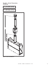
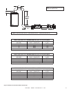
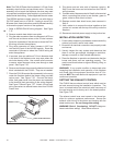
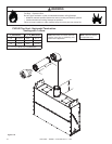
Mount and attach the power vent to the last vent system
component. The exhaust port of the PVK-80 cap MUST
be pointed down. Fasten the last horizontal vent section
to the exterior restop with a sheet metal screw through
the ange and into the vent pipe. See Figure 7.33.
NOTE: Wall restops (not included with the Power Vent)
are available for DVP vent pipe. The restop MUST be
used whenever a section of vent pipe passes through a
combustible wall.
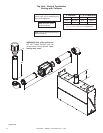
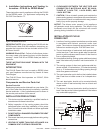
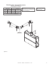
5. The minimum distance from the outside wall to the end
of the top shield of the PVK-80 horizontal cap is 14-1/2
inches. The maximum distance is 21 inches. See Figure
7.34.
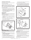
6. Two support braces are provided and MUST be used
to mount the PVK-80 horizontal cap to the wall. Screw
one end of each brace to the bottom of the cap housing,
using the pilot holes in the cap. Extend each brace until
it contacts the building wall and tighten the bolt/nut in
the center of each brace. Fasten the other end of each
brace to the outside wall. See Figure 7.34.
Figure7.32
Figure7.33
Figure7.34
FIBERGLASS TAPE
FOLD EDGE INSIDE PIPE
1 IN.
3 IN.
FAN EXHAUST PORT MUST BE DOWN
SUPPORT BRACES
14-1/2 in. MINIMUM
21 in. MAXIMUM
3 in.
1 in.
Note: Cut away
combustible
siding for proper
clearance.
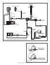
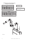
WIRINGTHEPVK-80POWERVENT
NOTE: Electrical wiring must be done in accordance with
national, provincial, and/or local electric codes.
CAUTION! Before performing any maintenance, repair,
or electrical wiring to the replace/power vent, make sure
the electrical power is rst disconnected to the replace/
power vent.
PLACE TERMINAL BLOCK BEHIND FAN.
ACCESS FROM FRONT
WIRE ACCESS HOLE
Figure7.35