


Heat & Glo • RED60 • 2159-900 Rev. R • 9/1238
IMPORTANTNOTE:When installing the PVK-80 with the
RED60 model, these PVK-80 installation instructions su-
percede the instructions that are included with the PVK-
80 Power Vent Kit.
WARNING! Risk of Fire! Failure to follow these instruc-
tions may create a re hazard and may void the replace
warranty. Install PVK-80 on RED60 model per these in-
structions.
THESE INSTRUCTIONS MUST REMAIN WITH THE
EQUIPMENT.
INTRODUCTION
The PVK-80 Power Vent can be used on RED60 direct
vent gas replaces manufactured by Hearth & Home
Technologies.
The PVK-80 Power Vent operates on 120VAC, 60Hz
electrical service.
ComponentsandServicePartsList
ServicePartsList
Replacement parts can be obtained from your dealer. Re-
pair of the Power Vent should only be done by a qualied
service technician. A list of replacement parts is shown in
the service parts section of this manual.
INSTALLATIONPRECAUTIONS
1. This device must be installed by a qualied installer in
accordance with these instructions.
2. Safety inspection of the venting system should be
performed before and after installation of this power
vent. Consult local code ofcials and follow applicable
installation codes.
3. DONOTINSTALLDAMAGEDEQUIPMENTORVENT
COMPONENTS.
4. Disconnect electrical power supply before making wiring
connections.
5. VENTINGOFMORETHAN ONEAPPLIANCEINA
COMMONVENTSYSTEMISPROHIBITED.
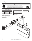
6. CLEARANCESBETWEENTHE VENTPIPEAND
COMBUSTIBLE MATERIALS MUST BE MAIN-
TAINED AT 3-INCH TOP, 1-INCH SIDES, AND
1-INCHBOTTOM.
7. CAUTION: Failure to install, operate, and maintain the
power venting system in accordance with manufacturer's
instructions will result in conditions which may produce
bodily injury and/or property damage.
NOTICE: The blower motor present in this appliance
will generate sound during operation. The effects of the
increased sound level can be minimized with careful
planning during installation of the system.
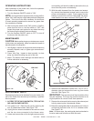
INSTALLATIONOFPVK-80
POWERVENT
1. Location of venting system terminations must be made
in accordance with national, provincial, and/or local
codes. The minimum clearance requirements must be
followed on models using the PVK-80 Power Vent.
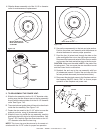
A. The exit termination of mechanical draft systems shall
not be less than 7 feet above grade when located ad-
jacent to public walkways and at least 10 feet from lot
line or adjacent buildings.
B. A mechanical drafting venting system shall terminate at
least 3 feet above any forced air inlet located within 10
feet.
C. The venting system of direct vent appliances shall ter-
minate at least 12 inches below, 12 inches horizontally
from, or 12 inches above any building opening through
which ue gases could enter.
D. The vent termination point shall not be installed closer
than 2 feet from an inside corner of an L-shaped struc-
ture.
E. The vent termination should not be mounted directly
above or within 3 feet horizontally from an oil tank vent
or gas meter.
F. The bottom of the vent termination shall be located at
least 2 feet above the nished graded and 2 feet above
any combustible projection.
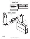
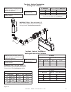
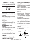
PVK-80 POWERVENT
Figure7.30PVK-80PowerVent
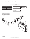
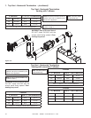
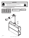
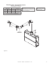
J. Installation Instructions and Venting In-
formation-PVK-80forRED60Model
These instructions are for appliances utilizing the PVK-80
for the RED60 model. For appliances incorporating the
PVI-DVP. See Section 7.F.
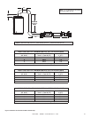
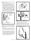
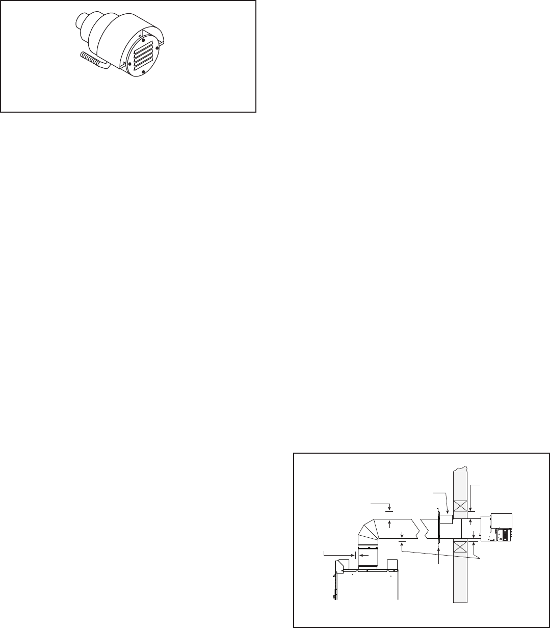
Figure7.31
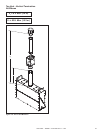
3 in. (76 mm)
top clearance *
1 in. (25 mm)
clearance
bottom & sides
Heat
Shield
Wall
Shield
Firestop
WALL
3 in. (76 mm)
top clearance
1 in. (25 mm)
clearance around
vertical sections