


Heat & Glo • RED60 • 2159-900 Rev. R • 9/1252
B. SecuringandLevelingtheAppliance
WARNING! Risk of Fire! Prevent contact with:
• Sagging or loose insulation
• Insulation backing or plastic
• Framing and other combustible materials
Block openings into the chase to prevent entry of blown-
in insulation. Make sure insulation and other materials
are secured.
DO NOT notch the framing around the appliance
standoffs. Failure to maintain air space clearance may
cause overheating and re.
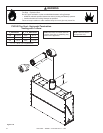
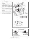
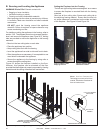
For details on setting the appliance in the framing, refer to
section 13.B. The diagram shows how to properly position,
level, and secure the appliance (see Figure 9.2). Nailing
tabs are provided to secure the appliance to the framing
members.
• Bend out the two nailing tabs on each side.
• Place the appliance into position.
• Keep nailing tabs ush with the framing.
• Level the appliance from side to side and front to back.
• Shim the appliance as necessary. It is acceptable to use
wood shims underneath the appliance.
• Secure the appliance to the framing by using nails or
screws through the nailing tabs.
Figure 9.2 shows the fireplace installed on the floor.
However, this fireplace can be elevated off the floor
provided that the replace is properly supported by framing
materials and the ceiling clearances are maintained.
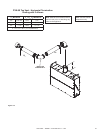
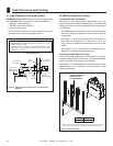
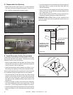
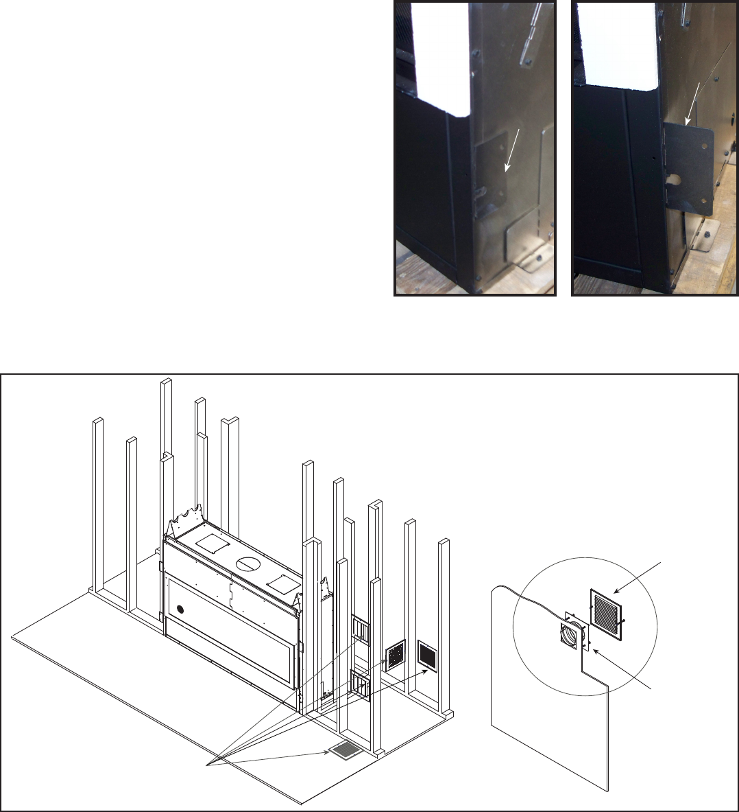
Figure9.2ProperPositioning,LevelingAndSecuringOfAnAppliance
POSSIBLE LOCATIONS FOR VENT
TERMINATION OF ACTIVE CONVECTION
TECHNOLOGY
DUCT COLLAR
ASSEMBLY
6 IN. X 5.5 IN. REQUIRED
GRILLE PANEL
TERMINATION INTO INTERIOR ROOM
N ot e: A ct iv e C on ve ct i on
Technology must not pull air from
outside. Termination must draw air
from an interior room.
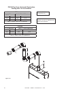
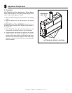
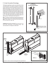
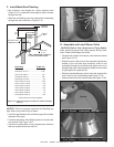
SettingtheFireplaceintotheFraming
The left and right nailing tabs were designed as a means
to ensure the replace is mounted ush with the framing
materials.
Bend out all four nailing tabs. Screw each nailing tab to
the adjoining framing material. Ensure that the one inch
air space clearance is maintained on the sides and back
of the replace. See Figure 9.3 and Figure 9.4.
Figure9.3NailingTabs
ShippingPosition
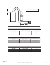
Figure9.4NailingTabs
InstallationPosition
NAILING
TAB
NAILING
TAB