


Heat & Glo • RED60 • 2159-900 Rev. R • 9/1228
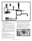
FAN
INTERMITTENT
PILOT IGNITOR
ORANGE
WHITE
SENSOR
WIRE
IGNITER
WIRE
6VDC TRANSFORMER
ELECTRICAL
ACCESS KNOCKOUT
APPLIANCE ON/OFF CONTROL
HARNESS
THERMO SNAP DISC
HARNESS
JUMPER
HARNESS
AUX300
MODULE
WALL SWITCH
JUMPER WIRE
ACCESSORY
CABLE
IPI WIRE
HARNESS
MALE/FEMALE
WIRE ASSEMBLY
8K1-PVI
TO PVI-DVP
ORANGE
GREEN
GREEN
VALVE
JUMPER
JUMPER
JUMPER
HI LIMIT SWITCHES
GROUND TO
FIREPLACE CHASSIS
JUNCTION BOX
TO FAN OUTLET
ON JUNCTION
BOX
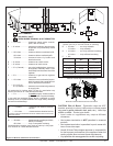
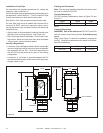
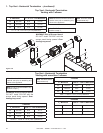
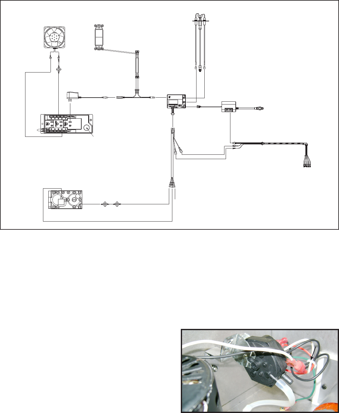
Figure7.17RED60PVI-DVPwithIntelliFirePlusPilotIgnitionWiringDiagram
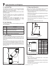
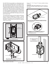
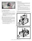
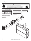
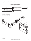
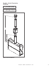
VacuumSwitchOrientation
WARNING! Risk of Fire and Explosion! Install vacuum
switch on a vertical plane. Failure to follow instructions could
result in re or explosion.
If the PVI is mounted in a vertical position, the vacuum
switch needs to be moved. To do this, loosen and remove
the two nuts currently using to secure it to the inside wall
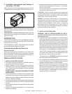
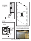
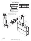
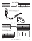
Figure7.18PVIHorizontalOrientation-SwitchandWire
InstallationInspection
1. Follow safety inspection procedures recommended by
national, provincial, and/or local codes.
2. Be certain all electrical connections are properly made
and secure.
3. Visually inspect the vent system and determine that
there is no ue gas spillage, blockage or restriction,
leakage, corrosion or other unsafe deciencies.
4. Place the replace in operation and determine that the
burner and power vent are operating properly. The
main burner should show no signs of oating, lifting, or
ashbacks.
WARNING: If any unsafe condition is determined when
inspecting the installation and operation of the replace
and Power Vent, the equipment should be shut off. Cor-
rections MUST be made before the equipment is put into
continuous operation.
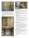
CAUTION: Risk of electrical shock! DO NOT allow 120VAC
wires to contact hot metal surfaces. Use supplied wire ties
to bundle wires away from ue pipe, blower housing and
other metal surfaces.
CAUTION! DO NOT allow wires to touch blower. Wire
insulation will melt. Power vent will malfunction.
ZIPTIE
of the PVI. Move and secure the vacuum switch onto the
adjacent wall using the two bolts that are sticking out of
the surface. See Figures 7.18 and 7.19 for reference.