


Heat & Glo • RED60 • 2159-900 Rev. R • 9/1242
OPERATINGINSTRUCTIONS
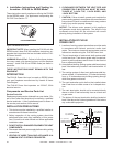
After installation of the power vent, follow the operation
instructions of the replace.
1. Turn the replace ON/OFF switch to "ON".
NOTE: During periods of operation after turning the re-
place "ON", there may be a slight delay before the replace
ignites. This is due to the time necessary for the blower
to reach operating speed and to remove any gases from
the combustion chamber.
2. After turning the switch to the "ON" position, if the re-
place does not turn on, shut the switch to "OFF" and
inspect the power vent system for any debris that may
be obstructing the blower blade movement.
3. Turn the replace ON/OFF switch to "OFF" to turn off
the burner and the power vent.
MAINTENANCE
CAUTION: Before performing any maintenance or repair
to the power vent assembly, make sure electrical power is
disconnected to the replace.
1. Vent System: Inspect all components and connections
annually. Replace, seal, or tighten pipe connections if
necessary.
2. Power Vent Cap: Inspect at least annually, to clear
away any debris blocking any part of the cap.
3. Motor: The blower motor bearings are sealed and no
further lubrication is necessary.
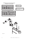
REPLACEMENTPARTS
Replacement parts can be obtained from your dealer. Re-
pair of the Power Vent should only be done by a qualied
service person.
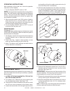
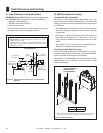
1. ACCESSTOTHEVACUUMSWITCH,TEFLONTUB-
ING,ANDBLOWERMOTOR:
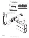
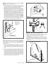
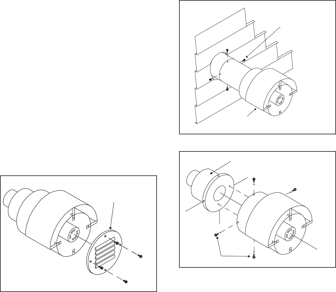
A. Turn power to off. Remove end cap by removing the
four (4) sheetmetal screws. See Figure 7.39.
B. Unplug the two wires connected to the vacuum switch
and the two wires connected to the blower motor.
C. Loosen and remove the nut for the right angle connector
and carefully pull back the cable to remove the four (4)
wires from the power vent assembly.
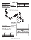
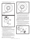
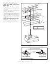
D. With the cable loosened from the power vent assem-
bly, remove the sheetmetal screws used to secure the
power vent assembly in place. Firmly support the as-
sembly to prevent the unit from falling after the sheet-
metal screws have been removed. See Figure 7.40.
END CAP
Figure7.39
REMOVE
SCREWS
SUPPORT WHEN
REMOVING
Figure7.40
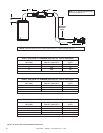
REMOVE SCREWS
INNER RING
Figure7.41
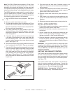
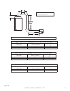
E. Remove the sheetmetal screws from the 10-1/2 in.
diameter pipe and remove the inner ring from inside
the collar. See Figure 7.41.
IMPORTANT: Take special note of the orientation of the
two part assembly. The inner ring must be returned to its
original position for correct Power Vent operation.
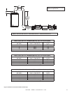
F. Remove the wire mesh that is covering the exhaust port
hole by removing the 4 sheetmetal screws.
G. Bend the metal guide plate at the exhaust port hole out
and through the hole on the 10-1/2 in. diameter collar.
See Figure 7.42.
Note: On some caps, the metal guide plate is attached to
the wire mesh and will slide out with the mesh.