


Heat & Glo • RED60 • 2159-900 Rev. R • 9/12 27
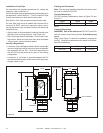
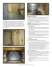
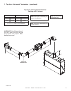
Figure7.13
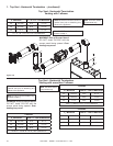
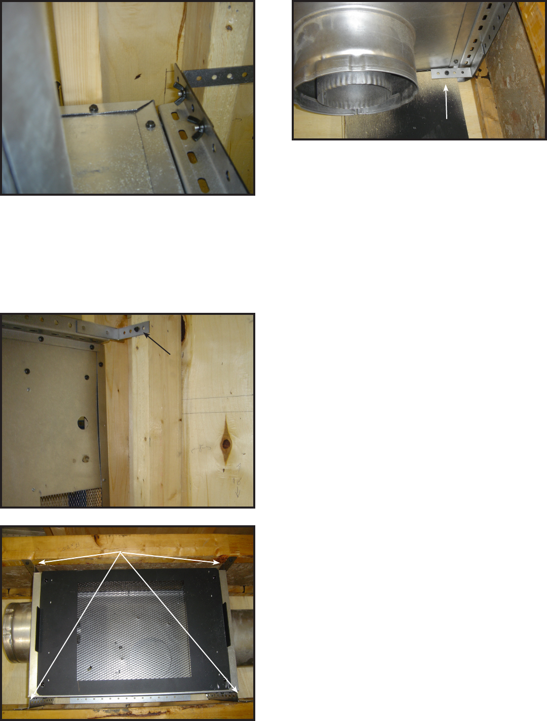
Figure7.14
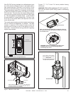
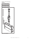
Figure7.15
SCREWS
SCREWS
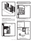
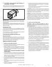
The optional mounting brackets may come in handy when
mounting the PVI to a studded wall. See Figure 7.13.
Securing the PVI inside a oor joist can be easily done us-
ing the side brackets. See gure 7.14. If the side brackets
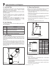
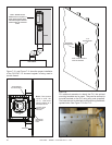
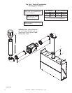
can’t be used, or additional support is needed, the optional
mounting brackets can be used as shown in Figure 7.15
and Figure 7.16.
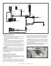
WiringthePVI-DVP
NOTICE: Electrical wiring must be done in accordance
with national, provincial, and/or local electric codes.
CAUTION: Risk of shock! Disconnect electrical power
from replace/power vent before performing any mainte-
nance, repair, or electrical wiring.
NOTICE: Electrical service of 120 VAC-60Hz must be
supplied to the junction box of the replace in order for the
power vent to operate correctly.
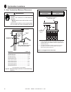
1.WireHarness
a. Determine the length of the wire harness required to
run between the PVI-DVP and the appliance from the
service parts list.
b. On the end closest to the junction box, drill a 7/8 inch
diameter hole and lead wire cable assembly through a
Romex connector.
c. Attach the end of the harness with the loose wires to
the PVI-DVP. Use supplied zip ties to contain all loose
wiring. See Figure 7.18 and Figure 7.19.
d. Attach the end of the harness with the connector to the
appliance.
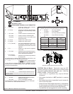
2.PVI-DVPConnections
Refer to the PVI-DVP wiring diagram (Figure 12.5).
a. Attach the green wire from the harness to the quick
ground connect. Connect the red wire to one of the
spades on the vacuum switch. Connect the brown wire
to the remaining spade on the vacuum switch.
b. Connect the white wire from the harness to the open
female connector on harness, inside the PVI.
c. Connect the black wire from the harness to the open
male connector on harness, inside the PVI.
3.RED60Connections
Refer to the RED60 wiring diagram, Figure 7.17. Ensure
wire harness has been fastened to the appliance. Route
wires and wire harness in a manner that protects them
from contact with sharp metal surfaces.
a. Attach the white, 3-wire connector to the AUX #2 con-
nector on the AUX300.
b. Connect the brown wire to the brown wire coming from
the 8K1-PVI.
c. Connect the red wire to the red wire coming from the
8K1-PVI.
Figure7.16
SCREWS