


Heat & Glo • RED60 • 2159-900 Rev. R • 9/12 25
If the PVI-DVP is being installed in a conned space (such
as a utility closet, mechanical room or attic space) with a
total volume less than 720 cubic ft, an 8 inch by 16 inch
hole will be required directly in front of the access panel.
The conned space where PVI is installed, and the space
to which the access hole opens, must add up to at least
720 cubic feet. This hole may be covered with a decora-
tive cover as long as the cover has a minimum of 50% open
air. This also applies to a replace chase. If the PVI-DVP
is being installed in a space greater than 720 cubic ft the
8 inch by 16 inch access hole is still required, but a solid
cover may be used.
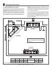
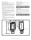
The access panel opening must be located such that ac-
cess for service and adjustment is available. The NEC
requires a minimum of 30 inches of space around the
opening and 36 inches in front of the opening to the ac-
cess panel. Consult ofcials having jurisdiction regarding
regional requirements.
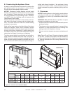
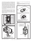
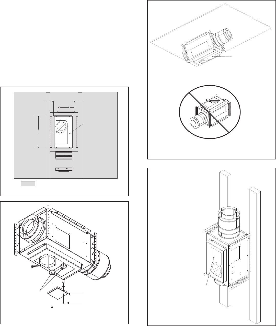
8 IN.
8 IN.
16 IN.
TOP
TOP
CENTER AIR
OPENING OVER COVER
= OPTIONAL FINISH MATERIAL AROUND ACCESS PANEL
Figure7.5AccessPanelFramingDimensions
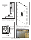
Figures 7.7, 7.8, 7.9 and 7.10 show possible framing
techniques.
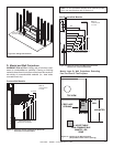
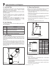
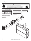
WARNING! Risk of re and burns! DO NOT install PVI-
DVP with the access panel facing upward. Overheating
may occur.
ACCESS PANEL
Figure7.7PVI-DVPMountedtoHorizontalSurface
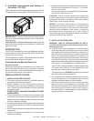
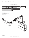
ACCESS PANEL
Note: AN 8 X 16 inch framed
hole is required in front of the
access panel.
This hole may be covered with
an open air louvered cover.
Figure7.8PVI-DVPMountedtoVerticalSurface
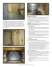
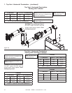
WARNING! Risk of fire and burns! DO NOT install
PVI-DVP with the access panel facing upward.
Overheating may occur.
Note: An 8 X 16 inch framed hole is required in front of
the access panel. This hole may be covered with an open
air louvered cover.
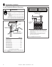
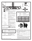
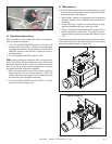
NOTE: When the PVI-DVP is installed in the upside-down,
horiztontal orientation, the supplied catch plate needs to
be mounted onto the cover assembly.
SCREWS
CATCH PLATE
CATCH PLATE HOLES
Figure7.6MounttheCatchPlate