


Heat & Glo • RED60 • 2159-900 Rev. R • 9/1224
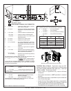
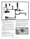
InstallationofVentPipe
For information on standard procedures for venting the
appliance, refer to Section 10.
For the allowable pipe lengths and elbow combinations for
this appliance, consult Section 7.I. The PVI uses DVP pipe
(8 inch) connections for both the inlet and outlet.
See Section 16 to view the approved termination caps.
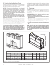
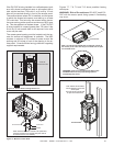
All outer pipe joints must be sealed with silicone with a
minimum of 300ºF continuous exposure rating, includ-
ing the slip section that connects directly to the horizontal
termination cap.
• Apply a bead of silicone sealant inside the female outer
pipe joint prior to joining sections. See Figure 10.2.
• Only outer pipes need to be sealed. All unit collar, pipe,
slip section, elbow and cap outer ues shall be sealed
in this manner, unless otherwise stated.
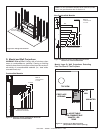
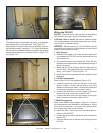
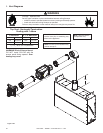
VentPipeRegulations
• A minimum of one 90 degree elbow and two feet straight
vertical or eight feet vertical venting is required between
the appliance and the PVI. Once this requirement is
met, the PVI may be placed at any point in the venting
conguration.
• A minimum of 18 inches is required between the PVI
and the termination cap to allow room for the pipe to go
through a wall or roof.
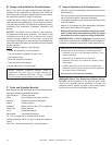
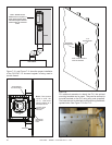
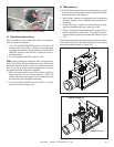
FramingandClearances
Note:The mounting brackets attached to the frame must
be used to install the PVI-DVP.
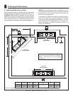
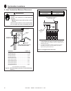
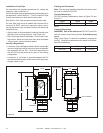
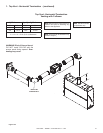
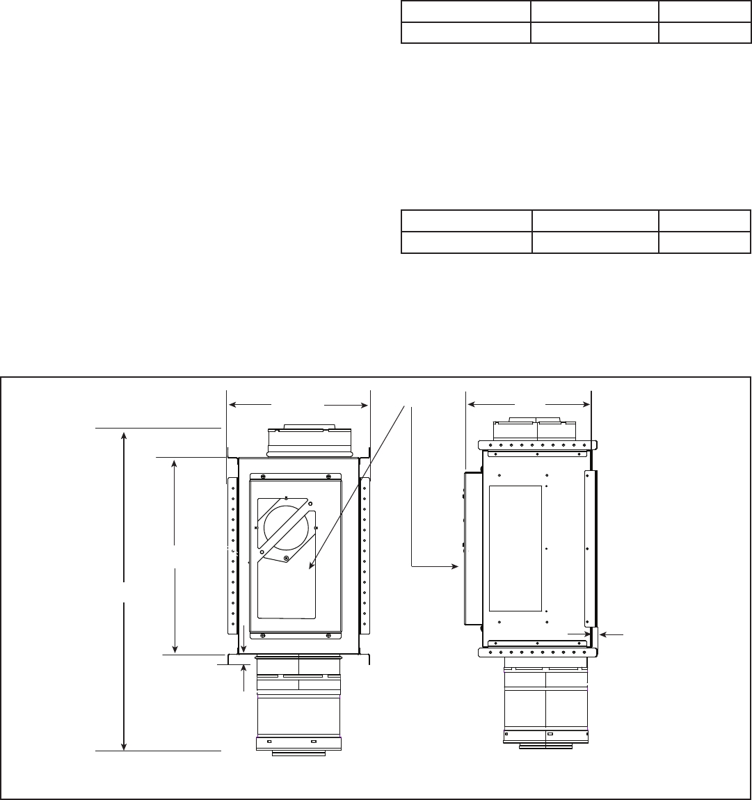
ChassisDimensions
PVI-DVP Vertically Positioned as shown in Figure 7.4 and
Figure 7.5.
Height Width Depth
18-7/8 in. 11-5/8 in. 13 in.
FramingDimensions
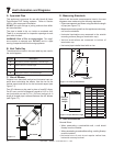
WARNING! Risk of re and burns! DO NOT install PVI
with the access panel facing upward. Overheating may
occur.
Table 2 and Figure 7.4 show the clearances required for
the PVI. Required clearances are the same for all allow-
able PVI orientations.
Height Width Depth
20-7/8 in. 13-5/8 in. 13-1/2 in.
Table1.
Table2.
18-7/8 IN.
11-5/8 IN.
1 IN.
CLEARANCE
13 IN.
1/2 IN. CLEARANCE
SIDE
ACCESS PANEL
30-11/16IN.
Figure7.4