


Heat & Glo • RED60 • 2159-900 Rev. R • 9/12 29
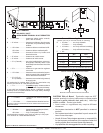
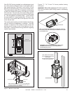
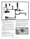
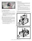
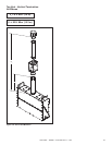
Figure7.19PVIVerticalOrientation-SwitchandWire
ZIPTIE
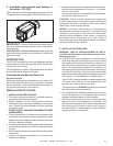
G.OperatingInstructions
After installation of the power vent, follow the operation
instructions of the replace.
1. Turn the ON/OFF/REMOTE switch on the black IPI
module to the ON position. When using a wall switch
to control the operation of the appliance, the ON/OFF/
REMOTE switch on the black IPI module must be in
the ON position.
2. Turn the replace ON/OFF switch to "ON".
Note: During periods of operation after turning the re-
place "ON", there will be a delay of at least 30 seconds
before the replace ignites. This is due to the time neces-
sary for the fan to reach operating speed and to remove
any gases from the combustion chamber.
3. After turning the switch to the "ON" position, if the re-
place does not turn on, shut the switch to "OFF" and
inspect the power vent system for any debris that may
be obstructing the fan blade movement.
4. Turn the replace ON/OFF switch to "OFF" to turn off
the burner and the power vent.
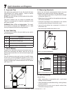
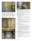
H.Maintenance
CAUTION: Before performing any maintenance or repair
to the power vent assembly, make sure electrical power
is disconnected to the replace.
1. Vent System: Inspect all components and connections
annually. Replace, seal, or tighten pipe connections if
necessary.
2. Power Vent Cap: Inspect at least annually, to clear
away any debris blocking any part of the cap.
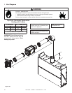
3. Motor: The blower motor bearings are sealed and no
further lubrication is necessary. To access the motor,
vacuum switch or pressure sense tube. Refer to Figure
7.20.
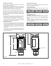
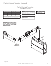
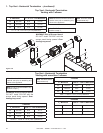
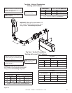
If the motor needs to be removed, take out the three screws
that attach the collar to the wall and the ve nuts holding
the motor down as shown in Figure 7.21.
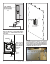
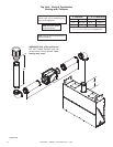
Figure7.20MotorandElectricalAccess
REMOVE SCREWS (3)
REMOVE NUTS (5)
Figure7.21MotorService