


Heat & Glo • RED60 • 2159-900 Rev. R • 9/12 53
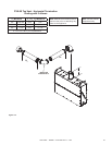
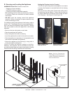
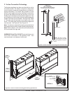
C. ActiveConvectionTechnology
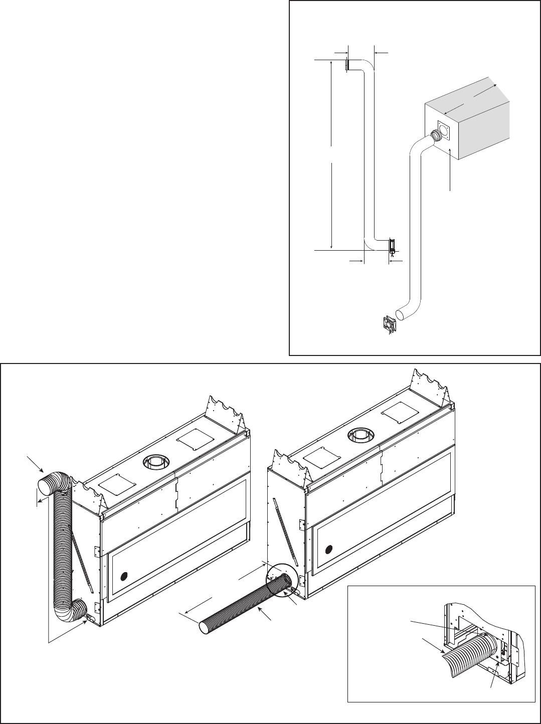
H2
V1
H1
H1 MAX. = 8 FT.
H1 + V1 + H2 = 8 FT.
MAX. = TWO 90° BENDS
INLET CONVECTION AIR MAY BE VENTED IN
ANY DIRECTION,INCLUDING DOWNWARD.
LOUVERED GRILLE
CLEARANCE FROM
INTAKE TO
OBJECTS = 24 IN. MIN.
24-IN. MIN.
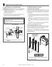
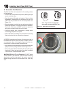
The replace appliance has been provided with an active
convection blower. The blower is required to keep lower
control chamber component temperatures at an ideal op-
erating temperature. The blower also provides for more
efcient use of appliance heat by assisting the convection
air around the rebox and back into the room. A four inch
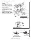
exible duct kit has been provided with the appliance. One
end of the ex duct will connect to the fan bracket assembly
located in the lower control chamber. See Figure 9.6, Detail
A. The other end will terminate to an interior wall of the
house. The intake grille panel provided with the appliance
must be used. See Figure 9.2 and Figure 9.5.
Note: The blower is essential for keeping components and
the appliance environment in safe operating temperatures.
Note: Refer to Section 12.C if the active convection blower
is to be moved to the right side.
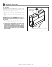
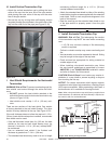
Figure9.6.ActiveConvectionTechnologyDuctVentingSpecications.
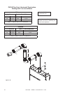
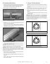
8 FT.
MAXIMUM
4 INCH
CONVECTION
AIR DUCT
MAX. OF 2
90° BENDS
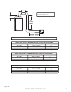
4 INCH
CONVECTION
AIR DUCT
8 FT.
MAXIMUM
SEE DETAIL A
DETAIL A
ZIP TIE
(INCLUDED WITH FLEX DUCT)
FAN BRACKET ASSEMBLY
4 INCH FLEX DUCT
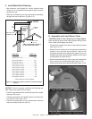
Figure9.5.ActiveConvectionTechnologyDuctandTermination.
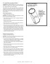
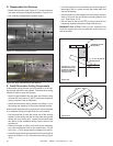
WARNING! Risk of Fire! DO NOT terminate blower vent
into an attic, crawl space, or the appliance chase. Vent
must terminate on an adjacent, interior wall.
NOTE: The 6 in. x 5.5 in.
intake grille panel provided
with the appliance must be
used.