


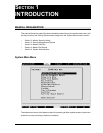
1-8 SECTION 1: INTRODUCTION
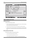
CREATING THE DATABASE
Once the system is in place, first obtain the following from the system installer:
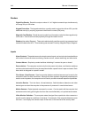
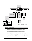
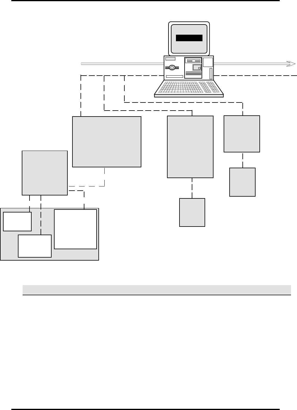
System Interconnect Diagram. This shows all wiring and connections in the system, and
provides information needed for entering pollers, devices, readers, and points.
Poller Initialization Parameters Information. The information shows how the pollers were
initialized, including poller type, physical port connection, and other poller-specific information.
Because all system activity is based on four-digit ID numbers, you need to decide before data entry
how these numbers are to be assigned to the system hardware elements. Although the numbering
system is entirely the choice of the SE 6000 owner, we recommend one of the two following
methods:
Alarm
Monitoring
Device
(Up to 16 per poller)
Contact Relays
(1—16)
1234 5678
Access Control Unit—
ACU
(Up to 16 per poller)
Sensor Connections
1 2 3 4 5 6 7 8
Contact
Switch
(Point)
Switcher
CCTV
Camera
Pollers
Multiple Switch
Monitor—MSM
Contacts
1 2 3 4
REX
(Point)
Reader
Door Switch
(Point)
One Complete Door
B
ASIC
SE 6000 S
YSTEM
SE 6000