


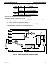

Optional Hardware and Software Model 360E Instruction Manual
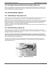
5.6. Oxygen Sensor (OPT 65)
5.6.1. Theory of Operation
5.6.1.1. Paramagnetic measurement of O
2
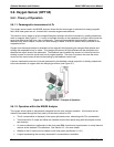
The oxygen sensor used in the M360E analyzer utilizes the fact that oxygen is attracted into strong magnetic
field; most other gases are not, to obtain fast, accurate oxygen measurements.
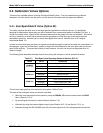
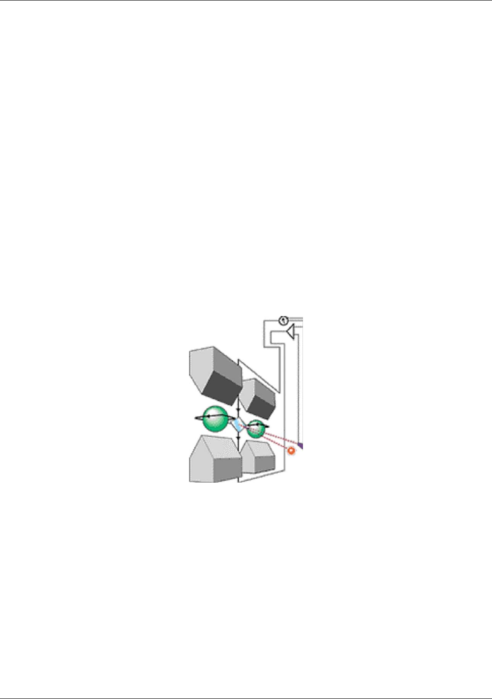
The sensor’s core is made up of two nitrogen filled glass spheres, which are mounted on a rotating suspension
within a magnetic field (Figure 5-7). A mirror is mounted centrally on the suspension and light is shone onto the
mirror that reflects the light onto a pair of photocells. The signal generated by the photocells is passed to a
feedback loop, which outputs a current to a wire winding (in effect, a small DC electric motor) mounted on the
suspended mirror.
Oxygen from the sample stream is attracted into the magnetic field displacing the nitrogen filled spheres and
causing the suspended mirror to rotate. This changes the amount of light reflected onto the photocells and
therefore the output levels of the photocells. The feedback loop increases the amount of current fed into the
winding in order to move the mirror back into its original position. The more O
2
present, the more the mirror
moves and the more current is fed into the winding by the feedback control loop.
A sensor measures the amount of current generated by the feedback control loop which is directly proportional
to the concentration of oxygen within the sample gas mixture (see Figure 5-7).
Figure 5-2: Oxygen Sensor - Principle of Operation
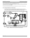
5.6.1.2. Operation within the M360E Analyzer
The oxygen sensor option is transparently integrated into the core analyzer operation. All functions can be
viewed or accessed through the front panel, just like the functions for CO
2
The O
2
concentration is displayed in the upper right-hand corner, alternating with CO
2
concentration.
Test functions for O
2
slope and offset are viewable from the front panel along with the analyzer’s other
test functions.
O
2
sensor calibration is performed via the front panel CAL function and is performed in a nearly identical
manner as the standard CO
2
calibration. See Section 3.3.1 for more details.
Stability of the O
2
sensor can be viewed via the front panel (see Section 3.3.2.1).
A signal representing the currently measured O
2
concentration is available.
46 05232 Rev B3