


Model 360E Instruction Manual MAINTENANCE SCHEDULE & PROCEDURES
9.3.4. Performing a Sample Flow Check
CAUTION
Always use a separate calibrated flow meter capable of measuring flows in the 0 – 1000
cc/min range to measure the gas flow rate though the analyzer.
DO NOT use the built in flow measurement viewable from the Front Panel of the
instrument. This measurement is only for detecting major flow interruptions such as
clogged or plugged gas lines.
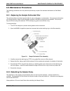
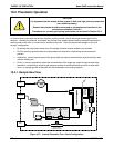
See Figure 3-2 for sample port location.
1. Attach the Flow Meter to the sample inlet port on the rear panel. Ensure that the inlet to the Flow Meter
is at atmospheric f.
2. Sample flow should be 800 cc/min 10%.
3. Once an accurate measurement has been recorded by the method described above, adjust the
analyzer’s internal flow sensors (See Section 6.13.8)
Low flows indicate blockage somewhere in the pneumatic pathway, typically a plugged sintered filter or critical
flow orifice in one of the analyzer’s flow control assemblies. High flows indicate leaks downstream of the Flow
Control Assembly.
9.3.5. Cleaning the Optical Bench
The M360E sensor assembly and optical bench is complex and delicate. Disassembly and cleaning is not
recommended. Please check with the factory before disassembling the optical bench.
9.3.6. Cleaning Exterior Surfaces of the M360E
If necessary, the exterior surfaces of the M360E can be cleaned with a clean damp cloth. Do not submerge any
part of the instrument in water or cleaning solution.
User Notes
05232 Rev B3 161