


Model 360E Instruction Manual THEORY OF OPERATION
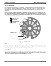
The four sample and hold circuits are:
ACTIVE WHEN: DESIGNATION
IR BEAM PASSING THROUGH SEGMENT SENSOR PULSE IS:
Measure Gate MEASUREMENT cell of GFC Wheel HIGH
Measure Dark Gate MEASUREMENT Cell of GFC Wheel LOW
Reference Gate REFERENCE cell of GFC Wheel HIGH
Reference Dark Gate REFERENCE cell of GFC Wheel LOW
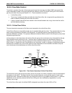
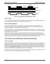
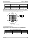
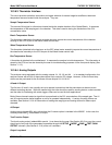
Timing for activating the Sample and Hold circuits is provided by a phase lock loop circuit (PLL). Using the
segment sensor output as a reference signal the PLL generates clock signal at ten times that frequency. This
faster clock signal is used by the PLD to make the sample and hold circuits capture the signal during the center
portions of the detected waveform, ignore the rising and falling edges of the detector signal.
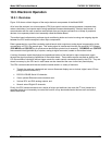
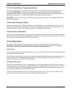
Sample & Hold
Active
Detector
Output
Sample & Hold
Inactive
Figure 10-13: Sample & Hold Timing
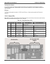
10.3.4.3. Sync/Demod Status LED’s
The following two status LED’s located on the synch/demod board provide additional diagnostic tools for
checking the GFC wheel rotation.
Table 10-1: Sync/Demod Status LED Activity
LED FUNCTION STATUS OK FAULT STATUS
D1
M/R Sensor Status
LED flashes approximately
2/second
LED is stuck
ON or OFF
D2 Segment Sensor
Status
LED flashes approximately
6/second
LED is stuck
ON or OFF
See Section 11.1.4 for more information.
05232 Rev B3 177