


THEORY OF OPERATION Model 360E Instruction Manual
10.2.3. Purge Gas Pressure Control
In order to ensure that all of the ambient CO
2
is purged from the GFC Wheel housing an adequate supply of
dried air, scrubbed of CO
2
must be supplied to the PURGE AIR inlet at the back of the instrument.
The minimum gas pressure of the source of purge air should be 7.5 psig.
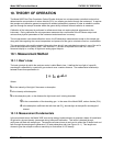
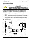
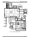
If the source of the purge air is shared by a Teledyne Instruments M700 (as shown in figure 3-7) the
minimum gas pressure should be 25 psig and should not exceed 35 psig.
In order to maintain the proper pressure differential between the inside of the GFC wheel housing and ambient
air, the M360 design includes a manually settable pressure regulator that maintains the pressure of the purge air
feed at 7.5 psig.
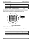
10.2.4. Particulate Filter
The Model 360E Analyzer comes equipped with a 47 mm diameter, Teflon, particulate filter with a 5 micron pore
size. The filter is accessible through the front panel, which folds down to allow access, and should be changed
according to the suggested maintenance schedule described in Table 9-1.
10.2.5. Pneumatic Sensors
10.2.5.1. Sample Pressure Sensor
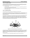
An absolute value pressure transducer plumbed to the outlet of the sample chamber is used to measure sample
pressure. The output of the sensor is used to compensate the concentration measurement for changes in air
pressure. This sensor is mounted to a printed circuit board with the sample flow sensor on the sample chamber;
see the following section and Figure 3-3.
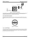
10.2.5.2. Sample Flow Sensor
A thermal-mass flow sensor is used to measure the sample flow through the analyzer. The sensor is calibrated
at the factory with ambient air or N
2
, but can be calibrated to operate with samples consisting of other gases
such as CO
2
, See Section 9.3.4. This sensor is mounted to a printed circuit board with the Sample Pressure
sensor on the sample chamber; see the previous section and Figure 3-3.
170 05232 Rev B3