


Model 360E Instruction Manual TROUBLESHOOTING & REPAIR PROCEDURES
1. For Pressure related problems:
Measure the voltage across C1 it should be 5 ± 0.25 VDC. If not then the board is bad.
Measure the voltage across TP4 and TP1. With the sample pump disabled it should be 4500 mV
±250 mV. With the pump energized it should be approximately 200 mV less. If not, then S1, the
pressure transducer is bad, the board is bad, or there is a pneumatic failure preventing the pressure
transducer from sensing the absorption cell pressure properly.
For flow related problems:
Measure the voltage across TP2 and TP1 it should be 10 ±0.25 VDC. If not then the board is bad.
Measure the voltage across TP3 and TP1. With proper flow (800 sccm at the sample inlet) this
should be approximately 4.5V (this voltage will vary with altitude). With flow stopped (sample inlet
blocked) the voltage should be approximately 1V. If the voltage is incorrect, the flow sensor is bad,
the board is bad or there is a leak upstream of the sensor.
11.5.7. Motherboard
11.5.7.1. A/D Functions
The simplest method to check the operation of the A-to-D converter on the motherboard is to use the Signal I/O
function under the DIAG menu to check the two A/D reference voltages and input signals that can be easily
measured with a voltmeter.
1. Use the Signal I/O function (See Section 11.1.3 and Appendix A) to view the value of REF_4
096_MV
and REF_GND. If both are within 3 mV of nominal (4096 and 0), and are stable, ±0.5 mV then the basic
A/D is functioning properly. If not then the motherboard is bad.
2. Choose a parameter in the Signal I/O function such as SAMPLE_PRESSURE, SAMPLE_FLOW,
CO
2
_MEASURE or CO
2
_REFERENCE. Compare these voltages at their origin (see interconnect
drawing 04215 and interconnect list 04216) with the voltage displayed through the signal I/O function. If
the wiring is intact but there is a large difference between the measured and displayed voltage (±10 mV)
then the motherboard is bad.
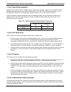
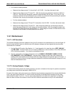
11.5.7.2. Analog Outputs: Voltage
To verify that the analog outputs are working properly, connect a voltmeter to the output in question and perform
an analog output step test as described in Section 6.9.3.
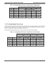
For each of the steps, taking into account any offset that may have been programmed into channel (See Section
6.9.4), the output should be within 1% of the nominal value listed in the table below except for the 0% step,
which should be within 2 to 3 mV. If one or more of the steps fails to be within this range then it is likely that
there has been a failure of the either or both of the DACs and their associated circuitry on the motherboard.
05232 Rev B3 213