M360E Documentation Model 360E Instruction Manual
2 05232 Rev B3
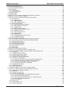
5.0 OPTIONAL HARDWARE & SOFTWARE
A description of optional equipment to add functionality to your analyzer.
6.0 OPERATION INSTRUCTIONS
This section includes step-by-step instructions for operating the analyzer and using its various features and
functions.
7.0 CALIBRATION PROCEDURES
General information and step by step instructions for calibrating your analyzer.
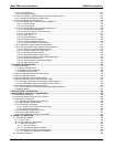
8.0 EPA PROTOCOL CALIBRATION
Because CO
2
is not declared a criteria air pollutant by the US EPA, EPA equivalency is not required for this type
of analyzer. Therefore no special calibration methods are needed to satisfy EPA requirements.
9.0 INSTRUMENT MAINTENANCE
Description of certain preventative maintenance procedures that should be regularly performed on you
instrument to keep it in good operating condition. This section also includes information on using the iDAS to
record diagnostic functions useful in predicting possible component failures before they happen.
10.0 THEORY OF OPERATION
An in-depth look at the various principals by which your analyzer operates as well as a description of how the
various electronic, mechanical and pneumatic components of the instrument work and interact with each other.
A close reading of this section is invaluable for understanding the instrument’s operation.
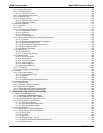
11.0 TROUBLESHOOTING:
This section includes pointers and instructions for diagnosing problems with the instrument, such as excessive
noise or drift, as well as instructions on performing repairs of the instrument’s major subsystems.
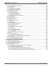
APPENDICES:
For easier access and better updating, some information has been separated out of the manual and placed in a
series of appendices at the end of this manual. These include: software menu trees, warning messages,
definitions of iDAS & serial I/O variables, spare parts list, repair questionnaire, interconnect listing and drawings,
and electronic schematics.
NOTE
Throughout this manual, words printed in capital, bold letters, such as SETUP or ENTR
represent messages as they appear on the analyzer’s front panel display.
NOTE
The flowcharts in this manual contain typical representations of the analyzer’s display
during the various operations being described. These representations are not intended
to be exact and may differ slightly from the actual display of your instrument.
User Notes


