


TROUBLESHOOTING & REPAIR PROCEDURES Model 360E Instruction Manual
11.2. Gas Flow Problems
The M360E has two main gas flow path, the sample gas flow path and the GFC purge gas flow path. Both are
controlled by a critical flow orifice. Only the sample gas path is measured and reported. When the IZS or
zero/span valve options are installed, there are several subsidiary paths but none of those are displayed on the
front panel or stored by the iDAS.
With the O
2
sensor option installed, third gas flow controlled with a critical flow orifice is added, but this flow is
not measured or reported.
In general, flow problems can be divided into three categories:
Flow is too high
Flow is greater than zero, but is too low, and/or unstable
Flow is zero (no flow)
When troubleshooting flow problems, it is crucial to confirm the actual flow rate without relying on the analyzer’s
flow display. The use of an independent, external flow meter to perform a flow check as described in Section
9.3.4 is essential. If this test shows the flow to be correct, check the pressure sensors as described in Section
11.5.6.5.
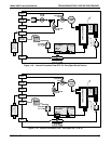
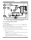
The flow diagrams found in a variety of locations within this manual depicting the M360E in its standard
configuration and with options installed can help in trouble-shooting flow problems. For your convenience they
are colleted here.
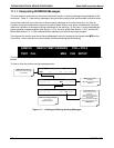
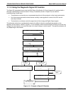
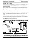
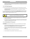
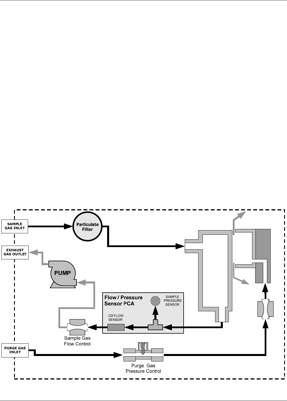
11.2.1. M360E Internal Gas Flow Diagrams
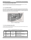
GFC Wheel
Housing
SAMPLE CHAMBER
GFC Motor
Heat Sync
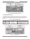
Purge Gas
Flow Control
Figure 11-7: M360E – Basic Internal Gas Flow
200 05232 Rev B3