


Operating Instructions Model 360E Instruction Manual
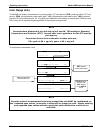
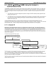
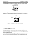
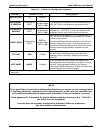
When COM2 is configured for RS-485 operation the port uses the same female DB-9 connector on the back of
the instrument as when Com2 is configured for RS-232 operation, however, the pin assignments are different.
Female DB-9
(
COM2
)
(As seen from outside analyzer)
(RS-485)
1 234 5
6 7 8 9
GND
RX/TX
+
RX/TX
-
Figure 6-11: Back Panel connector Pin-Outs for COM2 in RS-485 mode.
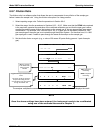
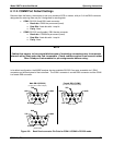
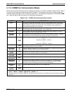
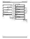
The signal from this connector is routed from the motherboard via a wiring harness to a 6-pin connector on the
CPU card, CN5.
CN5
(Located on CPU card)
(As seen from inside analyzer)
2 4 6
1 3 5
RX/TX
+
RX/TX
-
GND
Figure 6-12: CPU connector Pin-Outs for COM2 in RS-485 mode.
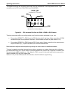
6.11.4. DTE and DCE Communication
RS-232 was developed for allowing communications between data terminal equipment (DTE) and data
communication equipment (DCE). Basic terminals always fall into the DTE category whereas modems are
always considered DCE devices. The difference between the two is the pin assignment of the Data Receive and
Data Transmit functions. DTE devices receive data on pin 2 and transmit data on pin 3; DCE devices receive
data on pin 3 and transmit data on pin 2.
To allow the analyzer to be used with terminals (DTE), modems (DCE) and computers (which can be either), a
switch mounted below the serial ports on the rear panel allows the user to switch between the two functions.
90 05232 Rev B3