


TROUBLESHOOTING & REPAIR PROCEDURES Model 360E Instruction Manual
11.5.6.2. Opto Pickup Assembly
Operation of the opto pickup PCA (04088) can be verified with a voltmeter. Measure the AC and DC voltage
between digital ground on the relay board, or keyboard and TP1 and TP2 on the sync pickup PCA. For a
working board, with the GFC motor spinning, they should read 2.4 ±0.1 VAC and 2.5 ±0.15 VDC.
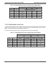
Further confirmation that the pickups and motor are operating properly can be obtained by measuring the
frequency at TP1 and TP2 using a frequency counter, a digital volt meter with a frequency counter, or an
oscilloscope per the table below.
Table 11-9: Opto Pickup Board Nominal Output Frequencies
NOMINAL MEASURED FREQUENCY
AC MAINS FREQ. TP1 TP2
50 Hz 25 300
60 Hz 30 360
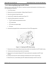
11.5.6.3. GFC Wheel Drive
If the D1 and D2 on the sync demodulator board are not flashing then:
1. Check for power to the motor by measuring between pins 1 and 3 on the connector feeding the motor.
For instruments configured for 120 or 220-240VAC there should be approximately 88 VAC for
instruments configured for 100VAC, it should be the voltage of the AC mains, approximately 100VAC.
2. Verify that the frequency select jumper, JP4, is properly set on the Relay Board. For 50 Hz operation it
should be installed. For 60 Hz operation may either be missing or installed in a vertical orientation.
3. If there is power to the motor and the frequency select jumper is properly set then the motor is likely bad.
See Section 11.6.2 for instructions on removing and replacing the
GFC assembly that the motor is
bolted to.
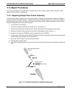
11.5.6.4. IR Source
The IR source can be checked using the following procedure:
1. Disconnect the source and check its resistance when cold. When new, the source should have a cold
resistance of more than 1.5 Ohms but less than 3.5 Ohms. If not, then the source is bad.
2. With the source disconnected, energize the analyzer and wait for it to start operating. Measure the drive
Voltage between pins 1 and 2 on the jack that the source is normally connected to; it should be 11.5 ±
0.25 VDC. If not, then there is a problem with either the wiring, the Relay Board, or the +12V power
supply.
3. If the drive voltage is correct in step 2, then remove the source from the heat sink assembly (2 screws
on top) and connect to its mating connector. Observe the light being emitted from the source. It should
be centered at the bottom of the U-shaped element. If there is either no emission or a badly centered
emission then the source is bad.
11.5.6.5. Pressure/Flow Sensor Assembly
The pressure/flow sensor PCA, located on the top of the absorption bench, can be checked with a Voltmeter
using the following procedure which, assumes that the wiring is intact, and that the motherboard and the power
supplies are operating properly:
212 05232 Rev B3