


TROUBLESHOOTING & REPAIR PROCEDURES Model 360E Instruction Manual
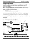
11.1.3. Using the Diagnostic Signal I/O Function
The Signal I/O parameters found under the DIAG Menu (See Section 6.9.2 and Appendix A) combined with a
thorough understanding of the instrument’s Theory of Operation (found in Chapter 10) are useful for
troubleshooting in three ways:
The technician can view the raw, unprocessed signal level of the analyzer’s critical inputs and outputs.
All of the components and functions that are normally under algorithmic control of the CPU can be
manually exercised.
The technician can directly control the signal level of the Analog and Digital Output signals.
This allows the technician to systematically observe the effect of directly controlling these signals on the
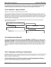
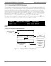
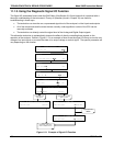
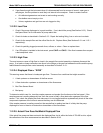
operation of the analyzer. Below in Figure 11-2 is an example of how to use the signal I/O menu to view the raw
voltage of an input signal or to control the state of an output voltage or control signal. The specific parameter will
vary depending on the situation.
Toggles parameter
ON/OFF
Exit returns to
DIAG display & all values
return to software control
DIAG SIGNAL I/O
PREV NEXT ENTR EXIT
DIAG I/O 0 ) EXT_ZERO_CAL=ON
PREV NEXT JUMP PRNT EXIT
DIAG I/O 22) WHEEL_HTR=ON
PREV NEXT JUMP ON PRNT EXIT
DIAG I/O 28) SAMPLE_PRESSURE=2540 MV
PREV NEXT JUMP PRNT EXIT
DIAG I/O 22 ) WHEEL_HTR=OFF
PREV NEXT JUMP OFF PRNT EXIT
If parameter is an
input signal
If parameter is an output
signal or control
SETUP X.X SECONDARY SETUP MENU
COMM VARS DIAG EXIT
SAMPLE ENTER SETUP PASS : 818
8 1 8 ENTR EXIT
SETUP X.X PRIMARY SETUP MENU
CFG DAS RNGE PASS CLK MORE EXIT
SAMPLE* RANGE = 500.000 PPM CO2 =X.XXX
< TST TST > CAL SETUP
Figure 11-2: Example of Signal I/O Function
196 05232 Rev B3