


THEORY OF OPERATION Model 360E Instruction Manual
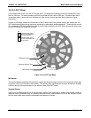
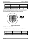
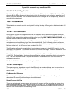
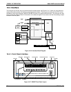
Figure 10
-14: Location of relay board Status LED’s
10.3.5.2. I
2
C Watch Dog Circuitry
Special circuitry on the relay board monitors the activity on the I
2
C bus and drives LED D1. Should this LED
ever stay ON or OFF for 30 seconds, the watchdog circuit will automatically shut of all valves as well as turn off
the IR Source and all heaters. The GFC wheel motor will still be running as will the Sample Pump, which is not
controlled by the relay board.
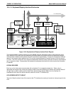
10.3.6. Mother Board
This printed circuit assembly provides a multitude of functions including, A/D conversion, digital input/output, PC-
104 to I2C translation, temperature sensor signal processing and is a pass through for the RS-232 and RS-485
signals.
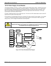
10.3.6.1. A to D Conversion
Analog signals, such as the voltages received from the analyzer’s various sensors, are converted into digital
signals that the CPU can understand and manipulate by the analog to digital converter (A/D). Under the control
of the CPU, this functional block selects a particular signal input (e.g. BOX TEMP, CO2 MEAS, CO2 REF, etc.)
and then coverts the selected voltage into a digital word.
The A/D consists of a voltage-to-frequency (V-F) converter, a programmable logic device (PLD), three
multiplexers, several amplifiers and some other associated devices. The V-F converter produces a frequency
proportional to its input voltage. The PLD counts the output of the V-F during a specified time period, and sends
the result of that count, in the form of a binary number, to the CPU.
The A/D can be configured for several different input modes and ranges but in the M360E is used in uni-polar
mode with a +5 V full scale. The converter includes a 1% over and under-range. This allows signals from –0.05
V to +5.05 V to be fully converted.
For calibration purposes, two reference voltages are supplied to the A/D converter: Reference Ground and
+4.096 VDC. During calibration, the device measures these two voltages, outputs their digital equivalent to the
CPU. The CPU uses these values to compute the converter’s offset and slope and uses these factors for
subsequent conversions.
See Section 6.13.4 for instructions on performing this calibration.
10.3.6.2. Sensor Inputs
The key analog sensor signals are coupled to the A/D through the master multiplexer from two connectors on
the motherboard. 100K terminating resistors on each of the inputs prevent cross talk from appearing on the
sensor signals.
Co
2
Measure And Reference
These are the primary signals that are used in the computation of the CO
2
concentration. They are the
demodulated IR-sensor signals from the sync demodulator board.
Sample Pressure And Flow
These are analog signals from two sensors that measure the pressure and flow rate of the gas stream at the
outlet of the sample chamber. This information is used in two ways. First, the sample pressure is used by the
CPU to calculate CO
2
Concentration. Second, the pressure and flow rate are monitored as a test function to
assist the user in predicting and troubleshooting failures.
180 05232 Rev B3