


Model 360E Instruction Manual THEORY OF OPERATION
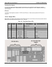
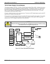
10.3.8. Power Supply/ Circuit Breaker
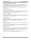
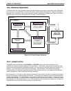
The analyzer operates on 100 VAC, 115 VAC or 230 VAC power at either 50Hz or 60Hz. Individual units are set
up at the factory to accept any combination of these five attributes. As illustrated in Figure 10-15, power enters
the analyzer through a standard IEC 320 power receptacle located on the rear panel of the instrument. From
there it is routed through the On/Off switch located in the lower right corner of the Front Panel. A 6.75 Amp
circuit breaker is built into the ON/OFF Switch.
AC power is distributed directly to the sample gas pump. The bench and GFC wheel heaters as well as the GFC
wheel receive AC power via the relay board.
AC Line power is converted stepped down and converted to DC power by two DC power supplies. One supplies
+12 VDC, for valves and the IR source, while a second supply provides +5 VDC and ±15 VDC for logic and
analog circuitry. All DC voltages are distributed via the relay board.
CAUTION
Should the AC power circuit breaker trip, investigate and correct the condition causing
this situation before turning the analyzer back on.
AC POWER
ENTRANCE
ON/OFF
SWITCH
Cooling Fan
Mother
Board
CPU
PS 1 (+5 VDC; ±15 VDC)
PS 2 (+12 VDC)
Display
Keypad
Pressure
Sensors
IR Source
Pump
GFC Wheel
Motor
Sync/Demod
M/R &
Segment
Sensors
Heaters
V
alve Options
KEY
AC POWER
DC POWER
RELAY
BOARD
Figure 10-15: Power Distribution Block Diagram
05232 Rev B3 183