


Model 360E Instruction Manual TROUBLESHOOTING & REPAIR PROCEDURES
11.5.7.4. Status Outputs
The procedure below can be used to test the Status outputs:
1. Connect a jumper between the “D“ pin and the “” pin on the status output connector.
2. Connect a 1000 ohm resistor between the “+” pin and the pin for the status output that is being tested.
3. Connect a voltmeter between the “” pin and the pin of the output being tested (see table below).
Under the DIAG SIGNAL I/O menu (See Section 11.1.3), scroll through the inputs a
nd outputs until you get to
the output in question. Alternately turn on and off the output noting the voltage on the voltmeter, it should vary
between 0 volts for ON and 5 volts for OFF.
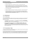
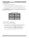
Table 11-12: Status Outputs Check
PIN (LEFT TO RIGHT) STATUS
1 SYSTEM OK
2 CONC VALID
3 HIGH RANGE
4 ZERO CAL
5 SPAN CAL
6 DIAG MODE
7 ALRM1
8 ALRM2
11.5.7.5. Control Inputs – Remote Zero, Span
The control input bits can be tested by the following procedure:
1. Connect a jumper from the +5 pin on the Status connector to the x5V on the Control In connector.
2. Connect a second jumper from the ‘-‘ pin on the Status connector to the A pin on the Control In
connector. The instrument should switch from SAMPLE mode to ZERO CAL R mode.
3. Connect a second jumper from the ‘-‘ pin on the Status connector to the B pin on the Control In
connector. The instrument should switch from SAMPLE mode to SPAN CAL R mode.
4. In each case, the M360E should return to SAMPLE mode when the jumper is removed.
05232 Rev B3 215