


THEORY OF OPERATION Model 360E Instruction Manual
10.2. Pneumatic Operation
CAUTION
It is important that the sample airflow system is both leak tight and not pressurized
over ambient pressure.
Regular leak checks should be performed on the analyzer as described in the
maintenance schedule, Table 9-1.
Procedures for correctly performing leak checks can be found in Section 9.3.3.
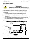
An internal pump evacuates the sample chamber creating a small vacuum that draws sample gas into the
analyzer. Normally the analyzer is operated with its inlet near ambient pressure either because the sample is
directly drawn at the inlet or a small vent is installed at the inlet. There are several advantages to this “pull
through” configuration.
By placing the pump down stream from the sample chamber several problems are avoided.
First the pumping process heats and compresses the sample air complicating the measurement
process.
Additionally, certain physical parts of the pump itself are made of materials that might chemically react
with the sample gas.
Finally, in certain applications where the concentration of the target gas might be high enough to be
hazardous, maintaining a negative gas pressure relative to ambient means that should a minor leak
occur, no sample gas will be pumped into the atmosphere surrounding analyzer.
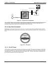
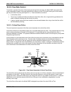
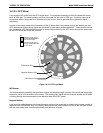
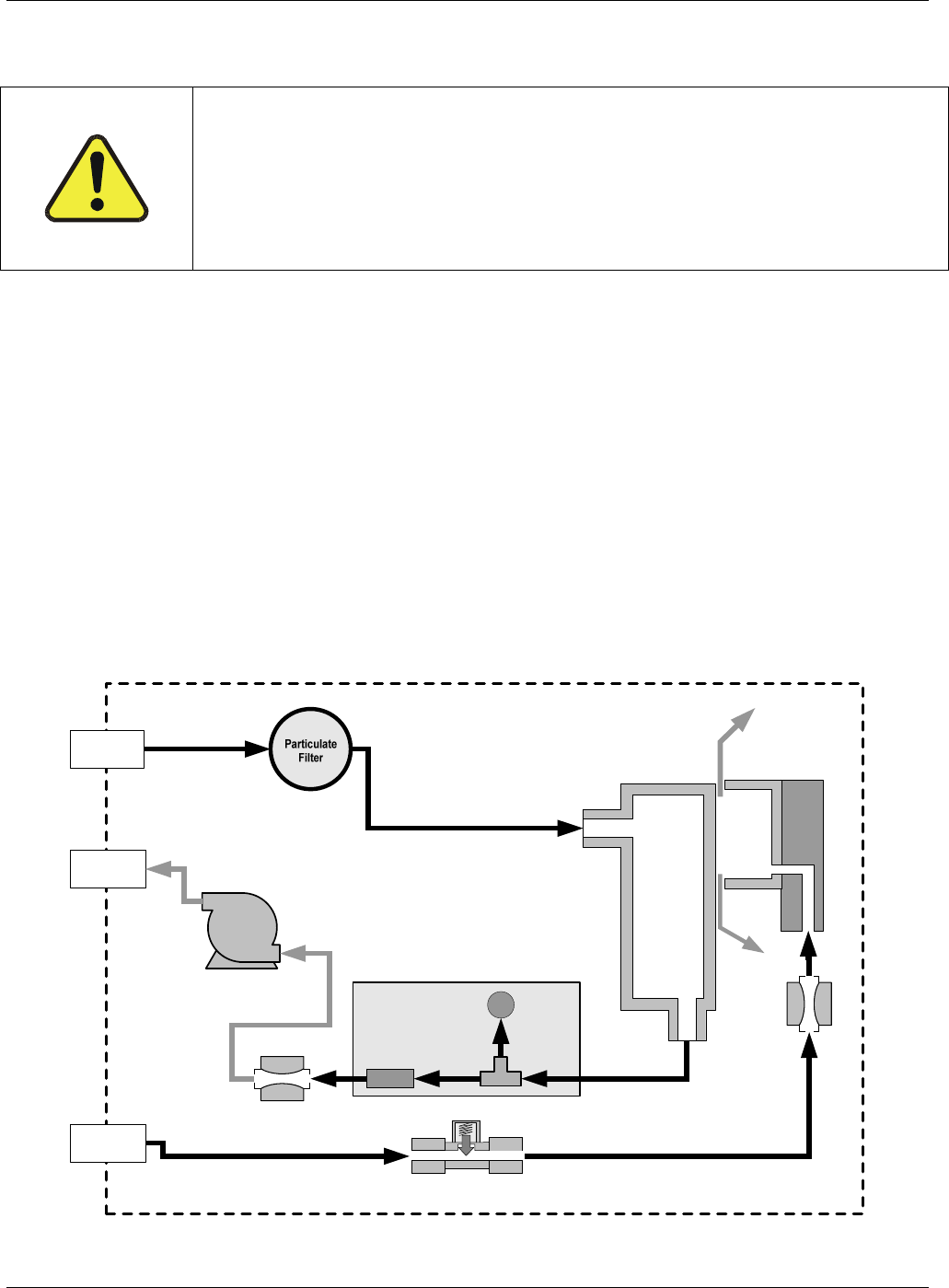
10.2.1. Sample Gas Flow
Flow / Pressure
Sensor PCA
SAMPLE
PRESSURE
SENSOR
O3 FLOW
SENSOR
SAMPLE GAS
INLET
EXHAUST
GAS OUTLET
GFC Wheel
Housing
SAMPLE CHAMBER
GFC Motor
Heat Sync
PUMP
PURGE GAS
INLET
Sample Gas
Flow Control
Purge Gas
Flow Control
Purge Gas
Pressure Control
Figure 10-7: Internal Pneumatic Flow – Basic Configuration
168 05232 Rev B3