


71
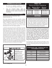
TABLE - EE
Maximum Flow Rate
Btu/hr Input Maximum Flow
1,500,000 - 2,000,000 90 GPM
If higher flow rates are required through the water heater, an
optional Cupro-Nickel heat exchanger is avail able. Consult the
factory for specific application requirements.
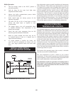
The heat exchanger is capable of op er at ing within the design flow
rates required for the water heater, storage tank(s) and connecting
piping. Erosion of the finned copper tubes may occur if the flow
rate exceeds the maximum al low able flow rate through the water
heater. The maximum flow through the water heater must be
adjusted with the bypass valve in the full closed po si tion. Maximum
flow is 90 GPM. Flow rate can be determined by measuring the
temperature rise through the water heater when it is firing at full
rate input. Also see Bypass Initial Setup of Maximum Water Flow
for adjustment procedure.
Setting temperature rise on an Intelli-Fin with an automatic bypass
is ac com plished by disconnecting the power leads to the actuator,
(multi-pin connector on rear of appliance), declutching the actuator
drive and manually closing the bypass valve. Manual adjustment
of the bypass must not be attempted if the 24 VAC power leads
are connected to the terminals on the appliance, the ap pli ance
is operating or if there is any torque on the bypass valve by the
ac tu a tor. Disconnect the 24 VAC power leads to the bypass
valve actuator. The declutch button on the actuator must be
pushed down and held in the depressed position to disengage the
gear driven motor that operates the valve. The declutch button must
push in easily without forcing its movement. If the button does not
easily move when pushed, the valve is under torque. Forcing the
declutch button in will cause non-warrantable damage to the
actuator. Torque can be removed by disconnecting the power leads
to the valve actuator. With the declutch button fully depressed,
move the ac tu a tor handle till it is perpendicular to the piping. This
fully closes the by pass valve. The position of the handle is the same
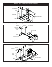
as the position of the butterfly in the valve seat. With the bypass
fully closed, all inlet water flows through the secondary heat ex -
chang er and then through the primary heat exchanger. No water
will flow through the bypass at this time. Turn the appliance on and
allow the burner to come on and fire at full rate (100% of input as
shown on the Command Dis play). Adjust the field-installed ball
valve in the outlet piping from the water heater to the storage tank
to achieve the proper temperature rise for your specific model.
Adjustment to achieve this temperature rise ensures a maximum of
90 GPM to the bypass and pump when in operation.
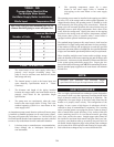
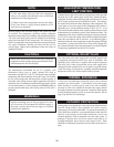
TABLE - FF
Temperature Rise At Full Rate Fire
Bypass Manually Fully Closed
Btu/hr Input Temperature Rise
1,500,000
_______________________
1,700,000
_______________________
2,000,000
31.5°F (17.5°C)
_______________________
35.7°F (19.8°C)
_______________________
42.0°F (23.3°C)
NOTE:
The Excel 10 controller makes all internal calculations in
°C and converts the displayed temperature to °F. This may
limit exact temperature adjustment. Setting of temperature
rise to the nearest °F is acceptable when setting maximum
flow.
1. The pump must run continuously when the burner is
firing.
2. With the pump running and the burner in the water
heater or hot water supply boiler in the off cycle,
the Return/Inlet Temp and Supply/Outlet Temp
readings on the Command Display should read
approximately the same tem per a tures. Temp Rise
in the Command Dis play should read zero.
3. Turn the water heater or hot water supply boiler
on and allow time for the temperature to stabilize.
Check the temperature rise in the Com mand
Display when the burner is firing at 100% of rated
input.
4. Compare the temperature rise on the Command
Display with the required tem per a ture rise. Should
adjustment be needed, proceed as follows:
If the temperature rise is too high, the water velocity is too
low. Adjust as follows:
1. Check for restrictions in the outlet of the water
heater or hot water supply boiler.
2. Check diameter and equivalent length of the piping
between the storage tank and water heater.
3. Be sure all valves are open between the water
heater or hot water supply boiler and the storage
tank. Ensure that all ball valves are fully ported.
4. Check the pump to be sure it is running properly
and that the pump motor is running in the proper
direction.