


63
FREEZE PROTECTION
CAUTIONƽ
Keep appliance area clear and free from combustible
materials, gasoline and other flammable vapors and
liquids.
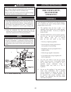
4. As the appliance comes on and fires, record the
inches of water column of displacement on both
sides of the manometer. The sum of these two
readings as they are effected by the two air
pressures is the differential air pressure.
5. The differential air pressure should be 3.5 inches
of water column (+ 0.1” w.c.) when the burner is
firing at 100% of rated input.
6. If the differential air pressure is not 3.5 inches
water column (+ 0.1” w.c.), review the installation.
Check for proper installation of the venting
system. Review the venting requirements in this
manual for the specific venting system installed
with this appliance. Correct as required. Ensure
that an adequate supply of combustion air is
supplied to the appliance. If a separate pipe is used
to supply combustion air, ensure that it is installed
per the combustion air pipe requirements
contained in the venting section of this manual.
Correct as required. Check the air inlet screen to
the combustion air blower. Clean as required.
Check the burner for dirt or contamination and
clean as required. Recheck for correct differential
air pressure after correcting an installation related
problem or after cleaning an obstructed
component. Ensure that a combustion air
differential of 3.5 inches water column (+ 0.1” w.c.)
is present while the appliance is firing at
100% of rated input.
7. This is a reference pressure only and is not field
adjustable. An appliance supplied with an
unrestricted supply of combustion air from a
correctly sized combustion air opening or separate
direct vent combustion air pipe will operate at the
correct air pressure differential as the burner input
varies with temperature demand.
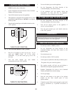
8. Close the two air pressure test cocks on the
pressure test tree and remove the hoses to the
manometer.
9. Close the front control panel.
L. COMBUSTIBLE MATERIALS
Installations are not recommended in areas where the danger of
freezing exists. Proper freeze protection must be provided for
appliances installed in unheated mechanical rooms or where
temperatures may drop to the freezing point or lower. If freeze
protection is not provided for the system, a low ambient temperature
alarm is rec om mend ed for the mechanical room. Damage to the
appliance by freezing is non-warrantable.
1. Pump Operation - MOST IMPORTANT - This
appliance is designed for con tin u ous pump
operation when the burners are firing. The integral
circulating pump will run continuously when the power
switch is in the “ON” position and the run/stop switch is
in the “RUN” position. As an optional feature an
intermittent pump control system can be provided. The
intermittent pump option allows the integral circulating
system pump to be cycled on at each call for heat and
cycled off when the set point is satisfied. The
intermittent pump will operate for a timed period after
the burner cycles off to remove residual heat from the
combustion chamber area. If the operating temperature
sensor for an intermittent pump system sees a drop in
water temperature to 45°F (7.2°C), the integral
circulating pump will cycle on. This flow of warm boiler
water can help prevent freezing.
2. Location - Heating boilers, hot water supply boilers
or water heaters must be located in a room having
a temperature safely above freezing [32°F(0°C)].
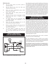
3. Caution - A mechanical room op er at ing under a
negative pressure may experience a downdraft in
the flue of an appliance that is not firing. The cold
outside air may be pulled down the flue and freeze
a heat exchanger. This condition must be corrected to
provide adequate freeze protection.
4. A motor driven damper may be installed in the air inlet to
prevent cold air movement in cold climates. The damper
MUST be interlocked with boiler/water heater controls to
open and prove on a call for heat.
5. Freeze protection for a heating boiler or hot water
supply boiler using an indirect coil can be provided by
using hydronic system antifreeze. Fol low the
manufacturers instructions. DO NOT use undiluted
or automotive type antifreeze.
6. Shut-down and Draining - If for any reason, the
unit is to be shut off, the following precautionary
measures must be taken:
(a) Shut off gas supply.
(b) Shut off water supply.
(c) Shut off electrical supply.