


67
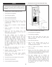
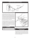
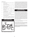
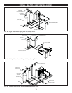
The automatic bypass system allows part of the boiler discharge water
to be mixed with the inlet water to the pri ma ry heat exchanger to
increase the boiler inlet temperature above 130°F (55°C). This will
prevent the products of combustion from condensing on the primary
heat exchanger. A valve must also be provided on the boiler dis charge,
after the bypass. Closing this discharge valve sets the maximum flow
through the appliance. (See Bypass—Initial Set-up of Maximum
Water Flow for more details.)
A minimum water temperature of 50°F (10°C) has been established
for each boiler based on the Btu/hr input at 100% of rated burner
input. The temperature set point for the Excel 10 controller sensing
system must not be set lower than the specified minimum for each
model. Maintaining inlet water temperatures to the boiler equal to
or higher than the specified minimum set point ensures proper
operation of the bypass and allows all condensate formation to
occur on the secondary heat exchanger. A boiler allowed to sustain
operation at water temperatures lower than the specified minimum
set point may not provide enough heat from the burner to maintain
water temper a tures in the primary heat exchanger above the 130°F
(55°C) dew point of flue products. Operation of a boiler at a
temperature below the specified minimum set point will result in
non-warrantable operational problems from the condensate
formation on the primary heat exchanger.
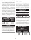
TABLE - CC
Minimum Inlet Water Temperatures
Input Minimum Return Minimum
Btu/hr Temperature Setpoint
1,500,000
_________
1,700,000
_________
2,000,000
105°F (40.6°C)
______________
90°F (32.2°C)
______________
70°F (23.9°C)
50°F (10°C)
__________________
50°F (10°C)
__________________
50°F (10°C)
CAUTIONƽ
A boiler allowed to operate at set point temperatures below
the spec i fied minimum settings may experience operational
problems with the operating controls and safety switches,
ob struc tion of the flue gas passages on the primary heat
exchanger, incomplete combustion and possible flue gas
spill age. Operation at lower than specified water
temperatures may cause hazardous conditions that result in
non-war rant able damage to the appliance.
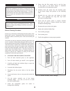
THREE WAY VALVES
The installation of a three way valve on this boiler is not
recommended be cause most piping methods allow the three way
valve to vary flow to the boiler. This boiler is a low mass, high
efficiency unit which requires a constant water flow rate for proper
operation. Low flow rates can result in overheating of the boiler
water which can cause short burner cycles, system noise, relief
valve discharge and in extreme cases, a knocking flash to steam.
These con di tions can cause operational problems and non-
warrantable failures of the boiler.
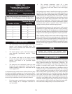
MAXIMUM FLOW FOR
HEATING BOILER
CAUTIONƽ
The maximum flow rate through the boiler with a copper
heat exchanger must not exceed the following:
Btu/hr Input Maximum Flow
1,500,000 - 2,000,000 90 GPM
If higher flow rates are required through the boiler, an optional
Cupro-Nickel heat exchanger is available. Consult the factory for
specific ap pli ca tion requirements.
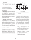
The heat exchanger is capable of op er at ing within the design flow
rates for the boiler secondary loop requirements. Erosion of the
finned copper tubes may occur if the flow rate exceeds the
maximum allowable flow rate through the boiler. The maximum
flow through the boiler must be adjusted with the bypass valve in
the full closed position. Maximum flow is 90 GPM. Flow rate can
be determined by measuring the tem per a ture rise through the boiler
when it is firing at full rate input. See Bypass-Initial Setup for
adjustment procedure.
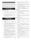
BOILER TEMPERATURE
RISE CHART
TABLE - DD
Temperature Rise at Full Rate Fire
Bypass Fully Closed and 90 GPM Flow
Btu/hr Input Temperature Rise
1,500,000
_______________________
1,700,000
_______________________
2,000,000
31.5°F (17.5°C)
________________________
35.7°F (19.8°C)
________________________
42.0°F (23.3°C)