


25
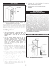
GAS PIPING
TRAP
GAS INLET
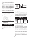
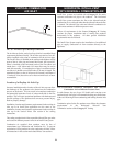
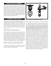
FIG. 34 Gas Line Connection to Unit with Sediment Trap
and Manual Main Gas Shut-off Valve
All gas connections must be made with pipe joint compound
resistant to the action of liquefied petroleum and nat u ral gas. All
piping must comply with local codes and ordinances. Tubing
installations must comply with approved standards and practices.
Install Piping to Control
1. The gas line should be a separate line direct from
the meter unless the existing gas line is of
sufficient capacity. Verify pipe size with your gas
supplier.
2. Use new, properly threaded black iron pipe free
from chips. If tubing is used, make sure the ends
are square, deburred and clean. All tubing bends
must be smooth and without deformation. Avoid
flexible gas connections. Internal diameter of
flexible gas lines may not provide appliance with
proper volume of gas.
3. Install a manual main gas shutoff valve at the units
gas inlet, outside of the appliance and before the
gas valve. Install a union at the ap pli ance gas
line connection for ease of service and removal of
the gas train.
4. Run pipe or tubing to the units gas inlet. If tubing
is used, obtain a tube to pipe coupling to connect
the tubing to the units gas inlet.
5. Install a sediment trap in the supply line to the
units gas inlet. (see Figure 34).
6. Remove seal over gas inlet to the appliance.
7. Apply a moderate amount of good quality pipe
compound (DO NOT use Teflon tape) to pipe only,
leaving two end threads bare.
8. Connect gas pipe to inlet of ap pli ance. Use wrench to
support gas man i fold on the appliance.
9. For LP gas, consult your LP gas supplier for expert
installation.
GAS MANIFOLD
PRESSURE ADJUSTMENT
The manifold gas pressure on the Intelli-Fin appliance is not field
adjustable. The ratio gas valve has been factory set with an internal
bias adjustment to ensure a 1:1 air/gas ratio on operation.
Tampering with this adjustment will void the warranty on the gas
valve assembly and the burn er. An Intelli-Fin supplied with a
properly sized gas line, properly sized meter and a minimum of 4
inch water column of gas supply pressure while firing at full rate
will ensure full burner in put. The manifold pressure supplied to the
burner is a differential pressure. This pressure is the result of the
difference in two gas pressure mea sure ments. A differential
manifold gas pressure measurement should not be made until you
have measured the gas supply pressure. Gas supply pressure must
be a minimum of 4 inch water column with all appliances on the
gas line firing at full rate before a manifold pressure measurement
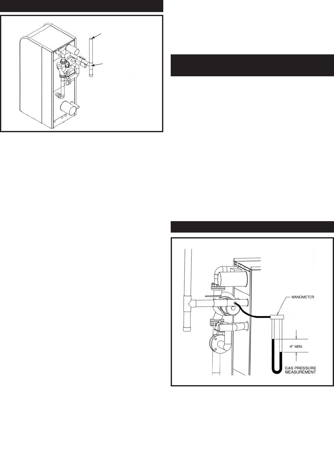
is made. Use the following pro ce dure to check gas supply pressure
with a manometer connected to the inlet pressure tap on the gas line
connection at the rear of the appliance.
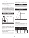
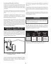
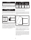
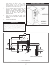
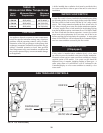
CHECKING GAS SUPPLY PRESSURE
FIG. 35 Gas Supply Pressure Measurement