


10
Any vent materials specified must be listed by a nationally
recognized test agency for use as a Category IV vent material.
The venting system must be planned so as to avoid possible
contact with con cealed plumbing or electrical wiring inside walls,
floors or ceilings. Locate the appliance as close as pos si ble to a
chimney or gas vent.
There shall be no reductions in vent diameter.
Horizontal portions of the venting system shall be supported to
prevent sagging. Horizontal runs should slope upwards not less
than 1/4 inch per foot (21 mm/m) from the drain tee installed in
the flue to the vertical portion of the flue or to the vent terminal
on sidewall venting installations. This ensures proper removal of
any con den sate that may form in the flue. Follow the installation
instructions from the vent material manufacturer.
Do not use an existing chimney as a raceway if another appliance
or fire place is vented through the chimney. The weight of the
venting system must not rest on the unit. Adequate support of the
venting system must be provided in compliance with local codes
and other applicable codes. All con nec tions should be secured
and sealed per the vent manufacturers specifications.
Vent connectors serving appliances vented by natural draft shall
not be connected to any portion of the Cat e go ry IV positive
pressure vent system used by this appliance. Connection of a
negative draft flue into the positive pressure stack from this
appliance may cause flue products to be discharged into an
occupied living space causing serious health injury.
When a Category IV vent system is dis con nect ed for any reason,
the flue must be reassembled and resealed according to the vent
manufacturer’s in struc tions.
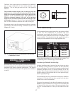
The installed length of the Category IV flue from the appliance
to the point of termination, outside of the building, must not
exceed a maximum of 100 equiv a lent feet (30.5 m) in length.
Subtract 5 feet (1.5 m) of equivalent length for each 90° elbow
installed in the vent. Subtract 2 1/2 feet (0.7 m) of equivalent
length for each 45° elbow installed in the vent.
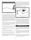
The flue may terminate either ver ti cal ly at the roof top or
horizontally on a sidewall. See the information about the specific
vent termination location for recommended location and
clearances.
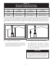
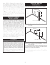
General Category IV Vent Termination Clearances
The vent cap should have a minimum clearance of 4 feet (1.2 m)
horizontally from and in no case above or below, unless a 4 foot
(1.2 m) horizontal dis tance is maintained from electric meters,
gas meters, regulators and relief equipment.
The venting system shall terminate at least 3 feet (0.9 m) above
any forced air inlet within 10 feet (3.05 m).
The venting system shall terminate at least 4 feet (1.2 m) below,
4 feet (1.2 m) horizontally from, or 1 foot (30 cm) above any
door, window or grav i ty air inlet into any building.
Do not terminate the vent in a window well, stairwell, alcove,
courtyard or other recessed area. The vent cannot terminate
below grade. The bottom of the vent terminal shall be located at
least 12 inches (30 cm) above grade and above normal snow levels.
To avoid a blocked flue condition, keep the vent cap clear of snow,
ice, leaves, debris, etc.
Flue gases from this appliance may contain large amounts of water
vapor that will form a white plume in winter. Plume could obstruct
a window view.
Flue gas condensate can freeze on ex te ri or surfaces or on the vent
cap. Fro zen condensate on the vent cap can result in a blocked flue
condition. Flue gas condensate can cause discoloration of exterior
building surfaces. Adjacent brick or masonry surfaces should be
protected with a rust re sis tant sheet metal plate.
The manufacturer shall NOT be held liable for any personal injury
or prop er ty damage due to ice formation or the dislodging of ice
from the vent system or the vent termination.
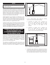
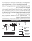
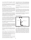
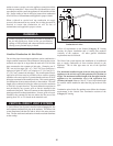
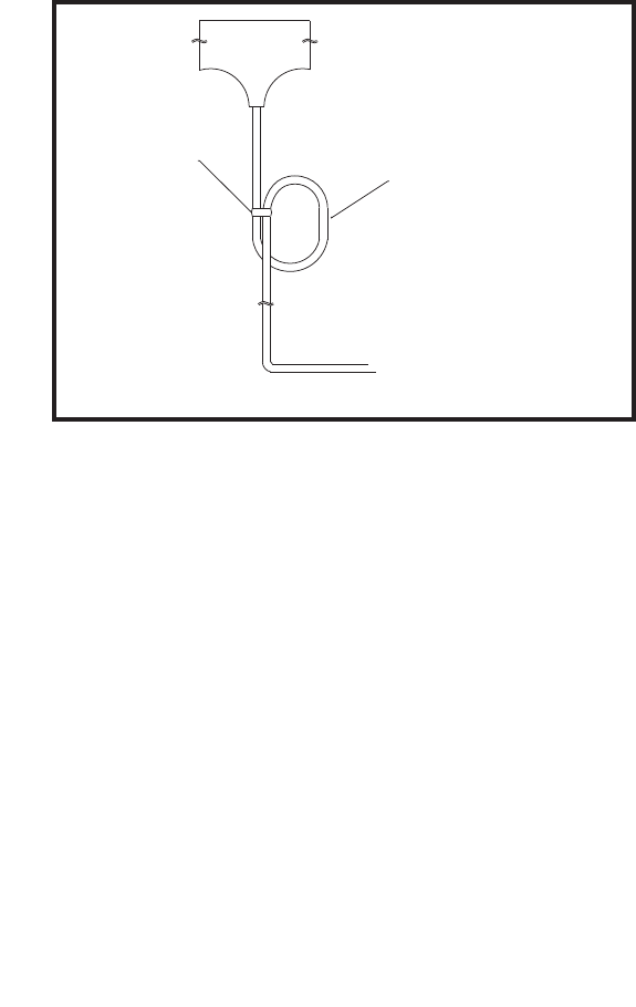
Drain Tee Installation
WIRE TIE
4" Ø
CIRCULAR TRAP
TO SUITABLE DRAIN
FIG. 12 Drain Tee
A drain tee MUST be installed in the Category IV vent pipe to
collect and dispose of any condensate that may occur in the vent
system. The drain tee should be installed at the point where the
flue turns vertical for a roof top termination or as one of the first
fittings in a horizontal flue that will terminate on a sidewall. Ensure
that horizontal portions of the vent are properly sloped to allow
condensate to be evacuated at the drain tee. See the typical vent
installation drawings. Plastic drain tubing, sized per the vent
manufacturer’s instructions, shall be provided as a drain line from