


7
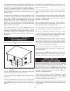
All dimensions based on net free area in square inches. Metal
louvers or screens reduce the free area of a com bus tion air opening
a minimum of ap prox i mate ly 25%. Check with louver
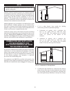
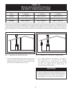
manufacturers for exact net free area of louvers. Where two
openings are provided, one must be within 12" (30 cm) of the
ceiling and one must be within 12" (30 cm) of the floor of the
mechanical room. Each opening must have net free area as
specified in Table - B. Single openings shall commence within 12"
(30 cm) of the ceiling.
The combustion air supply must be com plete ly free of any
flammable vapors that may ignite or chemical fumes which may
be corrosive to the appliance. Common corrosive chemical fumes
which must be avoided are fluorocarbons and other halogenated
compounds, most commonly present as refrigerants or solvents,
such as Freon, trichlorethylene, perchlorethylene, chlorine, etc.
These chemicals, when burned, form acids which quickly attack
the heat exchanger finned tubes, headers, flue collectors, and the
vent system. The result is improper combustion and a non-
warrantable, premature appliance failure.
These chemicals, when burned form acids which quickly attack the
boiler tubes, tube sheets, flue collectors, and the ap pli ance stack.
The result is improper combustion and a non-warrantable, pre ma -
ture failure of the appliance.
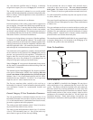
EXHAUST FANS: Any fan or equipment which exhausts air from
the equipment room may deplete the combustion air supply and/or
cause a downdraft in the venting system. Spillage of flue prod ucts
from the venting system into an occupied living space can cause a
very hazardous condition that must be im me di ate ly corrected. If a
fan is used to supply combustion air to the equipment room, the
installer must make sure that it does not cause drafts that could lead
to nuisance operational problems with the appliance.
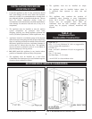
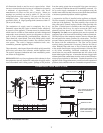
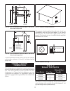
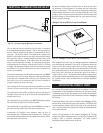
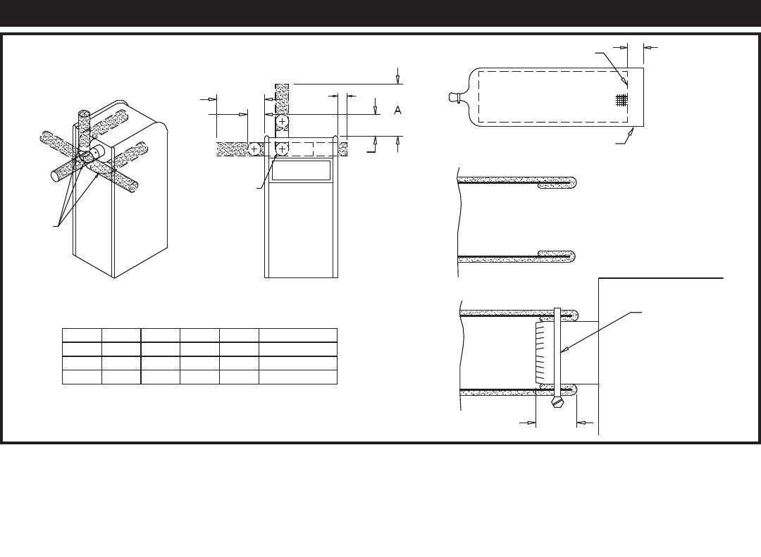
A construction air filter is installed on the ap pli ance as shipped.
The filter assembly is installed on the combustion air inlet located
at the rear of the appliance. The filter assembly slips over the air
inlet collar and is secured in place with the clamp provided with
the filter. If limited space is available at the rear of the appliance,
field supplied elbows may be used to mount the filter in the
alternate positions shown in the illustration. This filter is For
Temporary Use Only on an appliance that must be operated for
temporary heat or hot water when a building is under construction.
The filter will provide a temporary means to remove airborne dust,
dirt and particulate matter generated by construction. The filter
prevents airborne particulate contaminants from being drawn into
the burner with the combustion air. The filter can be cleaned
routinely during construction if necessary. Remove the filter to
clean. Wash the filter with water. A flow of water from the inside
to the outside should remove most particle matter. Allow the filter
to dry before reinstalling. Unfiltered com bus tion air from a
construction site can contain con tam i nants that will collect in the
burner reducing the firing rate. A burner that becomes clogged with
airborne particulate contaminants must be removed and cleaned to
restore proper operation to the burner. Sustained operation of an
appliance with a clogged burner may result in nuisance operational
prob lems, bad combustion and non-warrantable component failures.
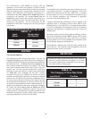
CONSTRUCTION AIR FILTER
9.000
ELBOW(S)
NOT
PROVIDED
CABINET AIR
INLET OPENING
D
E
C
B
EDGE OF SCREEN
2"
MEDIA OVERLAP
FOLD OVERLAP AROUND
EDGE OF SCREEN AS
SHOWN.
PUSH FILTER ONTO AIR
INLET AND FASTEN WITH
CLAMP AS SHOWN.
BAND CLAMP
2"
MODEL
A
B
C
D E REAR
2.0 19.750
12.250 4.875
15.000
24.000
1.7
1.5
19.250
18.750
10.750
9.250
4.375
3.875
6.000
7.500
14.000
24.000
14.500
24.000
FRONT
REAR
FIG. 9 Construction Air Filter