49
HOT SURFACE IGNITION SYSTEM
IGNITION CONTROL MODULE
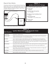
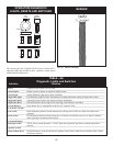
DIAGNOSTIC STATUS CODES
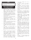
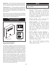
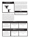
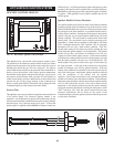
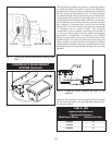
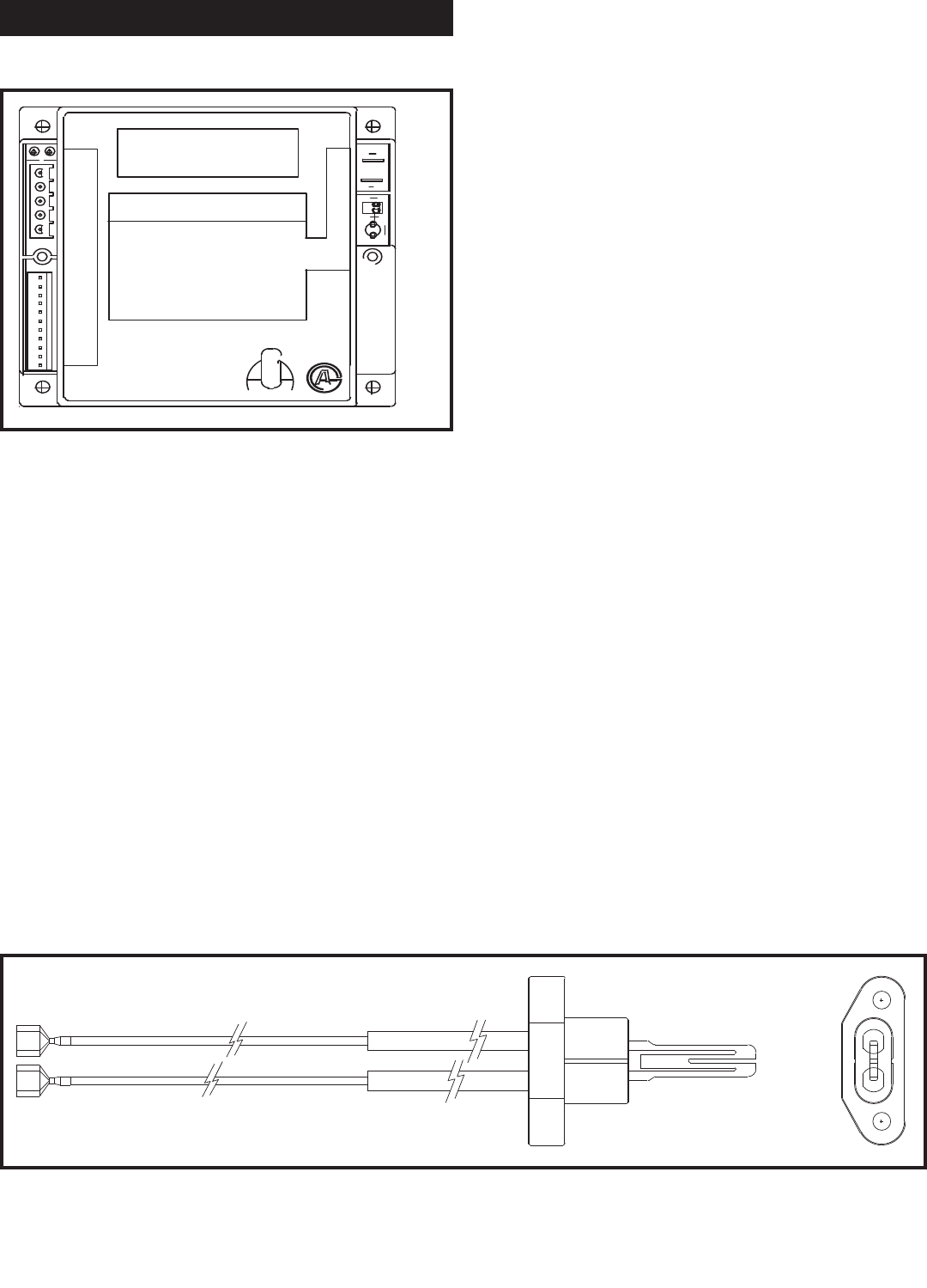
FIG. 63 Hot Surface Ignition Control Module
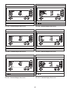
FIG. 64 Hot Surface Igniter
This appliance uses a proven hot sur face ignition control system.
The operation of the electronic control module for the hot surface
igniter proves the presence of an ignition source much like a proven
standing pilot before the gas valves are energized. The ignition
control module starts and proves the operation of the combustion air
blower, proves the presence of the proper ignition temperatures
from the hot surface igniter, energizes the main gas valves, proves
the presence of main burner flame, provides for soft lock outs on
control sensed faults, provides a hard lockout on flame failure and
controls the pre and post purge timings of the combustion air
blower. A status point alarm of FlameFail will be dis played in the
Command Display on a hard lockout for flame failure.
Service Parts
This appliance uses a proven electronic ignition control module and
a hot sur face igniter. The electronic ignition module is not
repairable. Any mod i fi ca tion or repairs will invalidate the warranty
and may create hazardous con di tions that result in property damage,
personal injury, fire, explosion and/or toxic gases. A faulty hot
surface igniter or ignition module MUST be replaced with a new
OEM unit only. An OEM specification igniter and ignition control
module for this specific unit is available from your local dis tributor.
DO NOT use general purpose field replacement ignition modules
or ig nit ers. Each appliance has one ignition module and one hot
surface igniter.
Ignition Module Lockout Functions
The ignition module may lockout in either a hard lockout condition
re quir ing pushing of the reset button to recycle the control or a soft
lockout condition which may recycle in a fixed time period to check
for correction of the fault condition. A typical hard lockout fault is
a flame failure con di tion. Pushing the reset button for the ignition
control is the only way to reset an ignition module that is in a hard
lockout condition. The reset button is located on the inside front
control panel. The reset button is active after the post purge cycle
when there is a hard lockout condition as indicated by the Status
LED. Turning the main power “OFF” and then “ON” or cy cling the
thermostat will not reset a hard lockout condition. Wait five
seconds after turning on the main power before pushing the reset
button when the ignition module is in a hard lock out. The ignition
module will go into a soft lockout in conditions of low air, low
voltage or low hot surface igniter current. A soft lockout con di tion
will operate the combustion air blower for the post purge cycle and
then the ignition module will pause for a fixed time period. The
timed length of the pause is based on the type of fault sensed by
the control module. At the end of this timed pause, the ig ni tion
module will attempt a new trial for ignition sequence. If the soft
lockout fault condition has subsided or has been corrected at the
end of the timed pause, main burner ignition should be achieved
with the resumption of the normal trial for ignition
se quence. If the control sensed fault is not corrected, the ignition
module will continue in the soft lockout condition. If the electronic
thermostat opens during the soft lockout period, the ignition module
will exit soft lockout and wait for a new call for heat from the
thermostat. A soft lockout con di tion may also be reset by manually
cycling the electronic thermostat or turning the main power switch
“OFF” and then “ON” after the control sensed fault has been
corrected. SoftLockout will be shown in the screen of the
Command Display when the ignition con trol module has gone into
a soft lock out condition.


