


38
Excel 10 Boiler Interface Controller - The boiler interface
control ler for this appliance is based on the Excel 10 controller
platform with unique software customized for op er a tion of the
Lochinvar Intelli-Fin. The Excel 10 is also compatible with
LonWorks
®
building management systems. All of the appliances’
internal safety, operating and ignition controls in ter face with the
Excel 10 controller. Local communication, programming and a
digital display of the appliance func tions and operating
conditions are accessible through a Command Display. The
Command Display is mounted on the front control panel of the
appliance as shipped from the manufacturer. If mul ti ple Intelli-Fin
appliances are to be installed in a single application, see
“Multiple Appliance Installations” for information on interfacing,
sequencing and display of multiple Intelli-Fin appliances.
NOTE:
A single Command Display is shipped for each job site
installation with up to 16 Intelli-Fin appliances. A
single Command Display is used to display and access
the operating conditions of up to 16 Intelli-Fin
appliances.
The Excel 10 Boiler Interface Control serves as the operating
temperature control to regulate the amount of heat added to the
water system for both heating boilers and potable water heat ers.
Custom software programmed into the Excel 10 will determine
the proper operating profile for your specific application. Ensure
that an Intelli-Fin is properly applied. A unit or dered as a heating
boiler must be ap plied as a heating boiler and a unit ordered as a
potable water heater must be applied as a water heater. The Excel
10 Boiler Interface Control provides on/off control of the gas
supply to the burner, operation of a VFD to control a variable
speed combustion air blower, interface with the ignition control
system, on/off control of the integral circulating pump, operation
of a float ing point bypass valve, control of water temperature set
points, and mon i tor ing of all safety functions. The operation and
status of these and all related functions are displayed on the
Command Display.
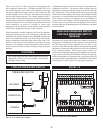
The Excel 10 has a single LED located in the middle of the control
module. In normal operation of a boiler equipped with an optional
outdoor reset function, this LED will blink at the rate of one blink
per second. Active alarms will blink this service LED at a faster
than normal rate of two blinks per second to indicate an alarm. The
alarms which are displayed in this manner are: Network
communications failure, sensor failure, hard lockout, water flow
failure, low air, blocked drain, low/high gas pressure, flame failure,
soft lockout, heat mode fail ure, high temperature alarm, and boiler
not operational. A boiler that is not equipped with the outdoor reset
func tion or a water heater will always blink the LED at the faster
rate of approximately two blinks per second. This LED is not to
be used as a di ag nos tic indicator.
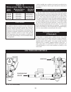
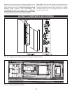
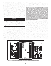
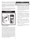
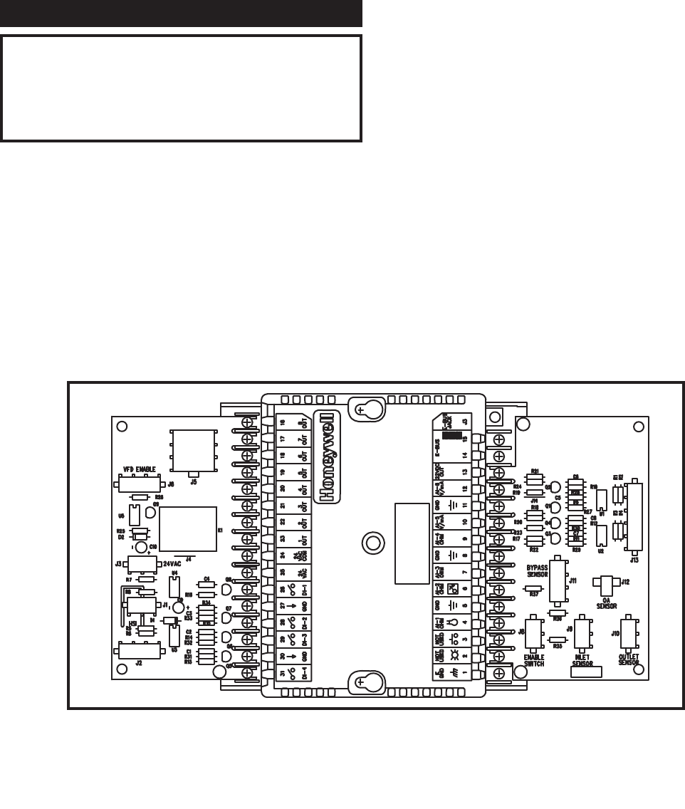
The Excel 10 controller is mounted on the backside of the front
control panel that mounts the Command Display and the Ignition
Control Module. This panel is hinged on the right side so it can be
exposed for viewing and service. All connections from the
appliance safety and operating controls to the Excel 10 are
accomplished with multiple wiring harnesses. Each wiring harness
is connected to unique multiple pin terminations to ensure proper
con nec tion of all components. The multiple termination points are
located on two printed circuit boards mounted on ei ther side of the
Excel 10 controller. Use caution when connecting or dis con necting
wires at the plug in terminals to prevent damage to the printed
circuit boards.
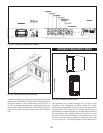
There is a bar code label on the back of the Intelli-Fin near the
terminal connections. This is the Neuron I.D. label which identifies
the exact nu mer i cal sequence applied to the Excel 10 control
installed in the boiler/water heater. This information is required for
the local/remote communication network. The numerical sequence
FIG. 53 Excel 10 Control Module with Circuit Boards and Wire Terminal Connections