27
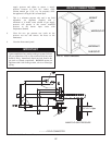
supply pressure and adjust to ensure a supply
pressure between 4.0 and 10.5 inches water
col umn natural gas (13.0" w.c. for propane) while
the appliance is firing at 100% of rated input.
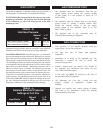
7. This is a reference pressure only and is not field
adjustable. An ap pli ance supplied with a
minimum of 4 inch es water column of gas supply
pres sure will operate at the correct man i fold
pressure as the burner input var ies with
temperature demand.
8. Close the two gas pressure test cocks on the
pressure test tree and remove the hoses to the
manometer.
9. Close the front control panel.
IMPORTANT
Upon completion of any testing on the gas system, leak test
all gas connections with a soap solution while the main
burner is firing. Immediately repair any leak found in the
gas train or related components. DO NOT operate an
appliance with a leak in the gas train, valves or related gas
piping.
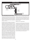
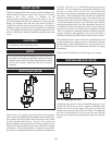
WATER CONNECTIONS
AIR INLET
GAS
WATER OUTL
ET
WATER INLET
FLUE OUTLET
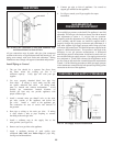
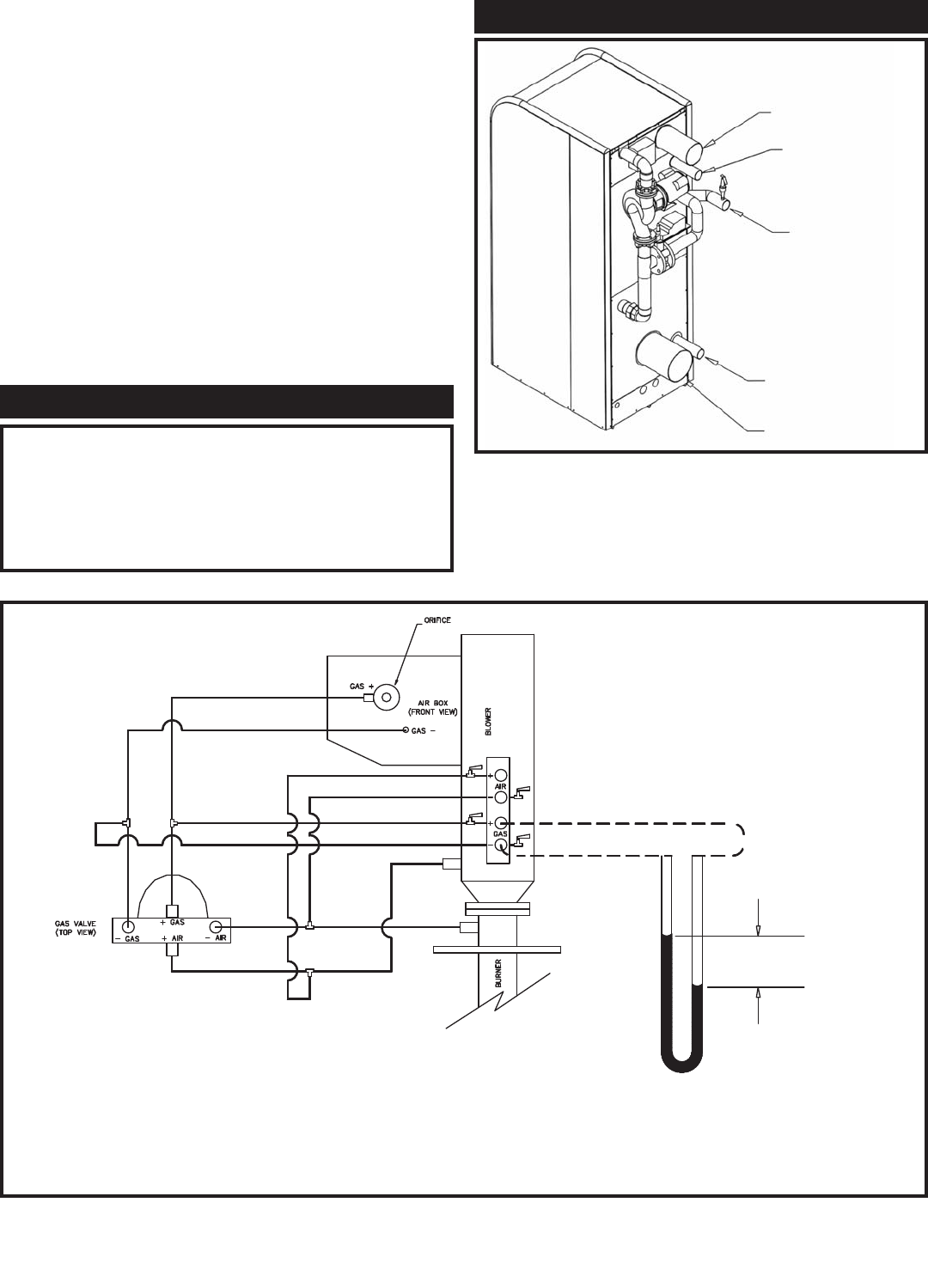
FIG. 37 Water Connections
– – – – = FIELD CONNECTED
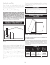
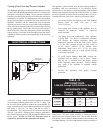
MANIFOLD GAS PRESSURE
3.5" W.C.= gas
P
FIG. 36 Manifold Gas Pressure Measurement


