


37
blower from 25% up to 100% of capacity corresponding to the
same variation in burner input. The output from the Excel 10 to
the variable frequency drive ensures that combustion air and gas
are always supplied in the proper ratio for clean combustion. The
vari able frequency drive is driven to 100% during the pre-purge
portion of the start-up sequence. The variable fre quen cy drive is
then provided a signal to operate at 50% for initial burner ignition.
After main burner ignition is established, the Excel 10 will use the
variable frequency drive to vary the blower speed based on desired
water temperature set point, the variation in actual water
temperature from the de sired set point and the various op er at ing
characteristics programmed into the control’s software.
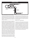
When removing the variable frequency drive from the appliance,
disconnect the power wires to the combustion air blower at the
terminals on the variable frequency drive. DO NOT disconnect the
power wires at the blower motor. Note the marking of the wires for
proper reinstallation of the three phase power wires to the VFD.
Both the wires and the VFD terminals are marked for proper
location of wire terminals. Incorrect installation of the wires may
reverse rotation of the blower motor resulting in major operational
problems.
CAUTIONƽ
The voltage output from the variable frequency drive to the
combustion air blower is 230 volt 3 phase. Avoid contact
with high voltage wiring.
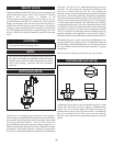
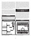
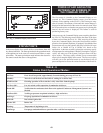
LOW AIR PRESSURE SWITCH
PRESSURE SWITCH
BLOWER
TRANSITION
BURNER
~
~
~
~
~
~
~
~
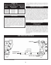
FIG. 51 Low Air Pressure Switch
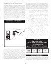
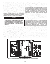
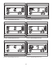
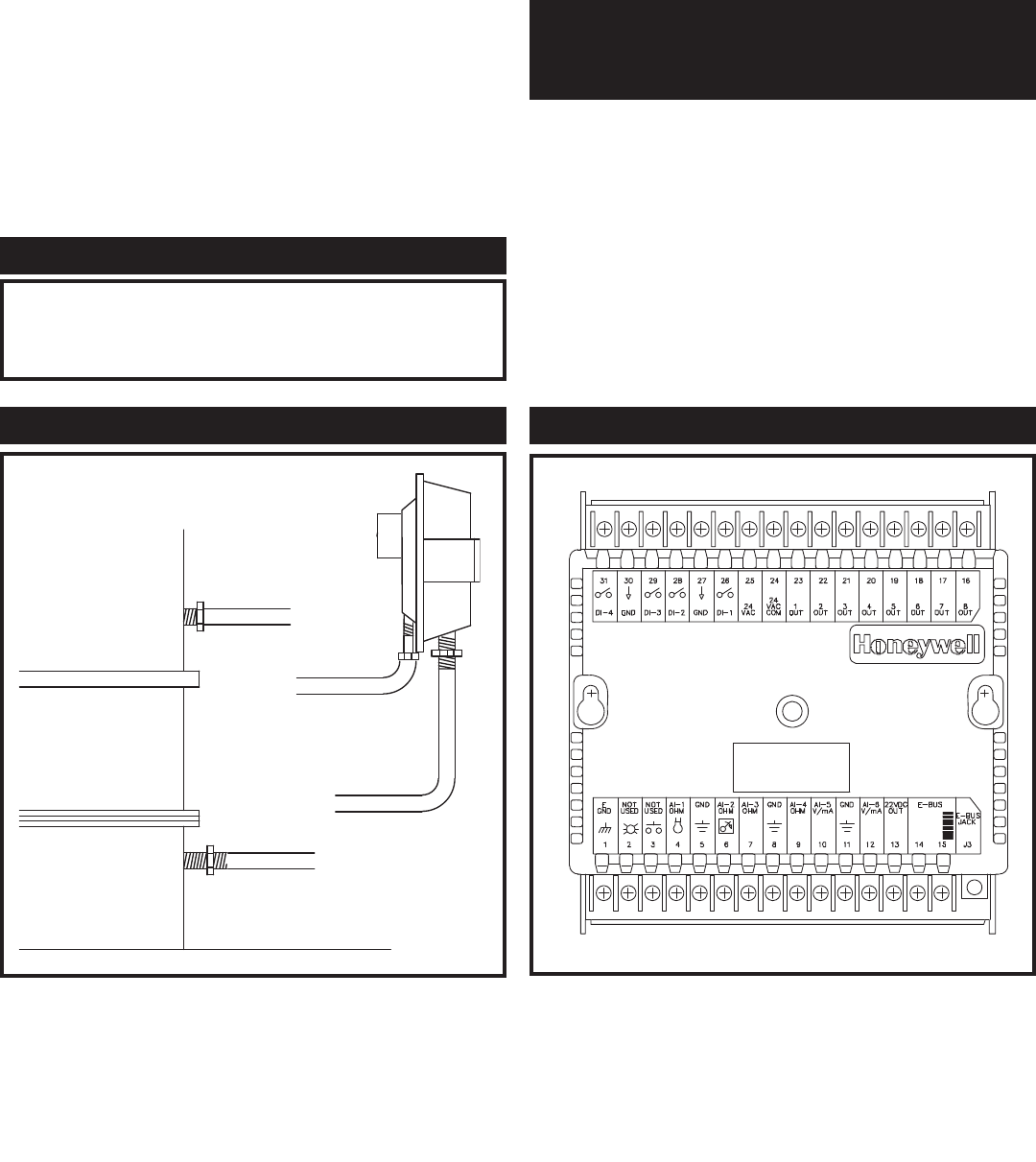
FIG. 52 Excel 10 Control Module
EXCEL 10
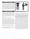
A differential air pressure switch is used to prove operation of the
com bus tion air blower. The pressure switch sensing points are
installed across the point of pressure drop as the air moves into the
inlet of the burner. This switch measures the same pressure drop
points similar to those used by the ratio gas valve to adjust manifold
gas pressure. Cor rect differential pressure across the sensing points
of the pressure switch proves operation of the combustion air
blower to the Excel 10 control. The Command Display will exhibit
a Status Alarm of LowAirPress and the appliance will shut down
operation when the differential pressure switch detects a sustained
low air condition.
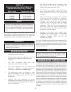
HIGH GAS PRESSURE SWITCH
LOW GAS PRESSURE SWITCH
(Optional)
High and/or low gas pressure switches are available as an option on
this appliance. The high gas pressure switch is used to monitor the
maximum gas supply pressure supplied to the gas train. If gas
pressure exceeds the maximum setting of the pressure switch, the
appliance will shut down and a gas pressure fault will be indicated
in the Command Display. The low gas pressure switch is to
monitor the minimum gas supply pressure supplied to the gas train.
If gas pressure falls below the minimum setting of the pres sure
switch, the appliance will shut down and a gas pressure fault will
be indicated on the Command Display. GasPressFail will be shown
on the Display for either a high or low gas pressure problem.